
Our heavyweight helicopter equal in the world does not have
In Rostov started production of the most load-lifting rotary-wing car The Russian holding «Helicopt[...]

Everything about aircrafts and helicopters. News and events in aviation worldwide. Civil, transportation, military helicopters and airplanes.

Everything about aircrafts and helicopters. News and events in aviation worldwide. Civil, transportation, military helicopters and airplanes.

Everything about aircrafts and helicopters. News and events in aviation worldwide. Civil, transportation, military helicopters and airplanes.

Everything about aircrafts and helicopters. News and events in aviation worldwide. Civil, transportation, military helicopters and airplanes.


Figures 3.12 (a)-(c) illustrate the flow states for the rotor in axial motion, i. e., when the resultant flow is always normal to the rotor disc, corresponding to hover, climbing or descending flight. The flow is assumed to be steady, inviscid and incompressible with a well-defined slipstream between the flowfield generated by the actuator disc (i. e., streamtube extending to infinity) and the external flow. Physically, this last condition is violated in descending flight when the flow is required to turn back on itself; we shall return to this point later. A further assumption we will make is that the pressure in the far wake returns to atmospheric. These assumptions are discussed in detail by Bramwell (Ref. 3.6) and Johnson (Ref. 3.7), and will not be laboured here. The simplest theory that allows us to derive the relationship between rotor thrust and torque and the rotor inflow is commonly known as momentum theory, utilizing the conservation laws of mass, momentum and energy. Our initial theoretical development will be based on the so-called global momentum theory, which assumes that the inflow is uniformly distributed over the rotor disc. Referring to Fig. 3.12, we note that T is the rotor thrust, v the velocity at various stations in the streamtube, vi the inflow at the disc, Vc the climb velocity and Vd the rotor descent velocity.
First, we shall consider the hover and climb states (Figs 3.12(a), (b)). If m is the mass flow rate (constant at each station) and Ad the rotor disc area, then we can write the mass flow through the rotor as
The rate of change of momentum between the undisturbed upstream conditions and the far wake can be equated to the rotor loading to give
t = m(Vc + vi) – tn Vc = m vi(З.120) where Vf^ is the induced flow in the fully developed wake.
The change in kinetic energy of the flow can be related to the work done by the rotor (actuator disc); thus
t (Vc + vi„) = іm (Vc + vi„)2 – іmvC = 2m (2^ + v?.) (3.121)
From these relationships we can deduce that the induced velocity in the far wake is accelerated to twice the rotor inflow, i. e.,
|
||
The expression for the rotor thrust can now be written directly in terms of the conditions at the rotor disc; hence
![]() T = 2 pAd (Vc + vi )vi
T = 2 pAd (Vc + vi )vi
Writing the inflow in normalized form
|
|
we may express the hover-induced velocity (with Vc = 0) in terms of the rotor thrust coefficient, Ct, i. e.,
|
|
|
|
![]()
The inflow in the climb situation can be written as
![]()
![]() Ct
Ct
2(Mc + ki)
or, derived from the positive solution of the quadratic
2
kih = (Mc + ki )ki
as
|
|
||
|
|||
where
_Vl a r
The case of vertical descent is more complicated. Strictly, the flow state satisfies the requirements for the application of momentum theory only in conditions where the wake is fully established above the rotor and the flow is upwards throughout the streamtube. This rotor condition is called the windmill brake state, in recognition of the similarity to a windmill, which extracts energy from the air (Fig. 3.12(c)). The work done by the rotor on the air is now negative and, following a similar analysis to that for the climb, the rotor thrust can be written as
T — 2pAd(Vd – vі)vi (3.130)
The inflow at the disc in the windmill brake state can therefore be written as
where
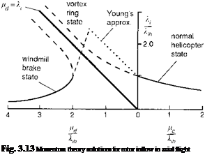 |
The ‘physical’ solutions of eqns 3.128 and 3.131 are shown plotted as the full lines in Fig. 3.13. The dashed lines correspond to the ‘unrealistic’ solutions. These solutions include descent rates from hover through to the windmill brake condition, thus encompassing the so-called ideal autorotation condition when the inflow equals the descent rate. This region includes the vortex-ring condition where the wake beneath the rotor becomes entrained in the air moving upwards relative to the rotor outside the wake and, in turn, becoming part of the inflow above the rotor again. This circulating flow forms a toroidal-shaped vortex which has a very non-uniform and unsteady character, leading to large areas of high inflow in the centre of the disc and stall outboard. The vortex-ring condition is not amenable to modelling via momentum considerations alone. However, there is evidence that the mean inflow at the rotor can be approximated by a semi-empirical shaping function linking the helicopter and windmill rotor states shown in Fig. 3.13. The linear approximations suggested by Young (Ref. 3.11) are
![]()
shown in the figure as the chain dotted lines, and these match the test data gathered by Castles and Gray in the early 1950s (Ref. 3.12) reasonably well. Young’s empirical relationships take the form
bi — 1 + 0 <—id <~1-5Xlh (3.133)
^ = ч (7 – 3- 1-5Xlh < – Ц. d < -2klh (3.134)
One of the important features of approximations like Young’s is that they enable an estimate of the induced velocity in ideal autorotation to be derived. It should be noted that the dashed curve obtained from the momentum solution in Fig. 3.13 never actually crosses the autorotation line. Young’s approximation estimates that the autorotation line is crossed at
— = 1.8 (3.135)
^ih
As pointed out by Bramwell (Ref. 3.6), the rotor thrust in this condition equates to the drag of a circular plate of the same diameter as the rotor, i. e., the rotor is descending with a rate of descent similar to that of a parachute.
Momentum theory in forward flight
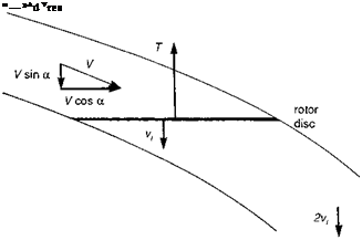
In high-speed flight the downwash field of a rotor is similar to that of a fixed-wing aircraft with circular planform and the momentum approximations for deriving the induced flow at the wing apply (Ref. 3.13). Figure 3.14 illustrates the flow streamtube, with freestream velocity V at angle of incidence a to the disc, and the actuator disc inducing a velocity vi at the rotor. The induced flow in the far wake is again twice the flow at the rotor (wing) and the conservation laws give the mass flux as
 |
(3.136)
and hence the rotor thrust (or wing lift) as
T = riilvi = 2p AdVresvi (3.137)
where the resultant velocity at the rotor is given by
Vr2s = (V cos ad)2 + (V sin ad + vt)2 (3.138)
Normalizing velocities and rotor thrust in the usual way gives the general expression
k = 1 == (3.139)
V[д2 + (ki – Hz )2]
where
and where ad is the disc incidence, shown in Fig. 3.14. Strictly, eqn 3.139 applies to high-speed flight, where the downwash velocities are much smaller than in hover, but it can be seen that the solution also reduces to the cases of hover and axial motion in the limit when h = 0. In fact, this general equation is a reasonable approximation to the mean value of rotor inflow across a wide range of flight conditions, including steep descent, and also provides an estimate of the induced power required.
Summarizing, we see that the rotor inflow can be approximated in hover and high-speed flight by the formulae
showing the dependence on the square root of disc loading in hover, and proportional to disc loading in forward flight.
Between hover and h values of about 0.1 (about 40 knots for Lynx), the mean normal component of the rotor wake velocities is still high, but now gives rise to fairly strong non-uniformities along the longitudinal, or, more generally, the flight axis of the disc. Several approximations to this non-uniformity were derived in the early developments of rotor aerodynamic theory using the vortex form of actuator disc theory (Refs 3.14-3.16). It was shown that a good approximation to the inflow could be achieved with a first harmonic with a linear variation along the disc determined by the wake angle relative to the disc, given by
where
k1cw — k0tan 2 ^ , X <
and the wake angle, x, is given by
where k0 is the uniform component of inflow as given by eqn 3.139.
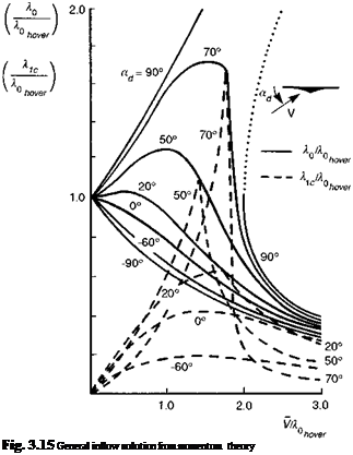 |
The solution of eqn 3.144 can be combined with that of eqn 3.139 to give the results shown in Fig. 3.15 where, again, ad is the disc incidence and Vis the resultant velocity of the free stream relative to the rotor. The solution curves for the (non-physical) vertical descent cases are included. It can be seen that the non-uniform component is approximately equal to the uniform component in high-speed straight and level flight, i. e., the inflow is zero at the front of the disc. In low-speed steep descent, the nonuniform component varies strongly with speed and is also of similar magnitude to the uniform component. Longitudinal variations in blade incidence lead to first harmonic lateral flapping and hence rolling moments. Flight in steep descent is often characterized by high vibration, strong and erratic rolling moments and, as the vortex-ring region is entered, loss of vertical control power and high rates of descent (Ref. 3.17). The
1.0 2.0 horizontal velocity parameter, V cos y/vh

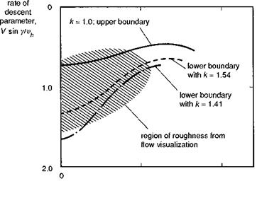 simple uniform/non-uniform inflow model given above begins to account for some of these effects (e. g., power settling, Ref. 3.18) but cannot be regarded as a proper representation of either the causal physics or flight dynamics effects; in particular, the dramatic loss of control power caused by the build up of the toroidal vortex ring is not captured by the simple model, and recourse to empiricism is required to model this effect. An effective analysis to predict the boundaries of the vortex-ring state, using momentum theory, was conducted in the early 1970s (Ref. 3.19) and extended in the 1990s using classical vortex theory (Ref. 3.20). Wolkovitch’s results are summarized in Fig. 3.16, showing the predicted upper and lower boundaries as a function of normalized horizontal velocity; the so-called region of roughness measured previously by Drees (Ref. 3.21) is also shown. The parameter k shown on Fig. 3.16 is an empirical constant scaling the downward velocity of the wake vorticity. The lower boundary is set at a value of k < 2, i. e., before the wake is fully contracted, indicating breakdown of the protective tube of vorticity a finite distance below the rotor. Knowledge of the boundary locations is valuable for including appropriate flags in simulation models (e. g., Helisim). Once again though, the simple momentum and vortex theories are inadequate at modelling the flow and predicting flight dynamics within the vortex-ring region. We shall return to this topic in Chapters 4 and 5 when discussing trim and control response.
The momentum theory used to formulate the expressions for the rotor inflow is strictly applicable only in steady flight when the rotor is trimmed and in slowly varying conditions. We can, however, gain an appreciation of the effects of inflow on rotor thrust during manoeuvres through the concept of the lift deficiency function (Ref. 3.7). When the rotor thrust changes, the inflow changes in sympathy, increasing for increasing thrust and decreasing for decreasing thrust. Considering the thrust changes
as perturbations on the mean component, we can write
![]()
![]() SCt = 5Cres + (^l)Qs Ski where, from the thrust equation (eqn 3.91)
SCt = 5Cres + (^l)Qs Ski where, from the thrust equation (eqn 3.91)
d Ct a()S
dki ) qs 4
and where the quasi-steady thrust coefficient changes without change in the inflow. Assuming that the inflow changes are due entirely to thrust changes, we can write
5ki = C SCt (3.148)
The derivatives of inflow with thrust have simple approximate forms at hover and in forward flight
|
dki d Ct |
1 = —, v = 0 4k |
(3.149) |
|
dki „ d Ct |
» —, v > 0.2 2v |
(3.150) |
Combining these relationships, we can write the thrust changes as the product of a deficiency function and the quasi-steady thrust change, i. e.,
SCT = C ‘SCTqs (3.151)
where
C = , V = 0 (3.152)
1 + 16ki
and
C = V > 0.2 (3.153)
1 + 8v
Rotor thrust changes are therefore reduced to about 60-70% in hover and 80% in the mid-speed range due to the effects of inflow. This would apply, for example, to the thrust changes due to control inputs. It is important to note that these deficiency functions do not apply to the thrust changes from changes in rotor velocities. In particular, when the vertical velocity component changes, there are additional inflow perturbations that lead to even further lift reductions. In hover, the deficiency function for vertical velocity changes is half that due to collective pitch changes, i. e.,
|
|||
|
|||
|
|
||
sensitivity of rotors increases strongly from hover to mid speed, but levels out to the constant quasi-steady value at high speed (see discussion on vertical gust response in Chapter 2).
Because the inflow depends on the thrust and the thrust depends on the inflow, an iterative solution is required. Defining the zero function g0 as
g0 = 10 -(2S/2) (3 ‘551
where
Л = p2 + (10 – Pz)2 (3.156)
and recalling that the thrust coefficient can be written as (eqn 3.91)
+ 4 + p2) &t
(3.157)
Newton’s iterative scheme gives
 10j+1 = – Ц + fjhj( 10 j)
where
i. e.,
For most flight conditions the above scheme should provide rapid estimates of the inflow at time tj+1 from a knowledge of conditions at time tj. The stability of the algorithm is determined by the variation of the function g0 and the initial value of I0. However, in certain flight conditions near the hover, the iteration can diverge, and the damping constant f is included to stabilize the calculation; a value of 0.6 for f appears to be a reasonable compromise between achieving stability and rapid convergence (Ref. 3.4).
A further approximation involved in the above inflow formulation is the assumption that the freestream velocity component normal to the disc (i. e., V sin ad) is the same as pz. This is a reasonable approximation for small flapping angles, and even for the larger angles typical of low-speed manoeuvres the errors are small because of the insensitivity of the inflow to disc incidence (see Fig. 3.15). The approximation is convenient because there is no requirement to know the disc tilt or rotor flapping relative to the shaft to compute the inflow, hence leading to a further simplification in the iteration procedure.
The simple momentum inflow derived above is effective in predicting the gross and slowly varying uniform and rectangular, wake-induced, inflow components. In practice, the inflow distribution varies with flight condition and unsteady rotor loading (e. g., in manoeuvres) in a much more complex manner. Intuitively, we can imagine the inflow varying around the disc and along the blades, continuously satisfying local flow balance conditions and conservation principles. Locally, the flow must respond to local changes in blade loading, so if, for example, there are one-per-rev rotor forces and moments, we might expect the inflow to be related to these. We can also expect the inflow to take a finite time to develop as the air mass is accelerated to its new velocity. Also, the rotor wake is far more complex and discrete than the uniform flow in a streamtube assumption of momentum theory. It is known that local blade-vortex interactions can cause very large local perturbations in blade inflow and hence incidence. These can be sufficient to stall the blade in certain conditions and are important for predicting rotor stall boundaries and the resulting flight dynamics at the flight envelope limits. We shall return to this last topic later in the discussion on advanced, high-fidelity modelling. Before leaving inflow however, we shall examine the theoretical developments needed to improve the prediction of the non-uniform and unsteady components.
