
Our heavyweight helicopter equal in the world does not have
In Rostov started production of the most load-lifting rotary-wing car The Russian holding «Helicopt[...]

Everything about aircrafts and helicopters. News and events in aviation worldwide. Civil, transportation, military helicopters and airplanes.

Everything about aircrafts and helicopters. News and events in aviation worldwide. Civil, transportation, military helicopters and airplanes.

Everything about aircrafts and helicopters. News and events in aviation worldwide. Civil, transportation, military helicopters and airplanes.

Everything about aircrafts and helicopters. News and events in aviation worldwide. Civil, transportation, military helicopters and airplanes.


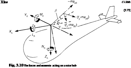 |
Returning to the fundamental frames of reference given in Appendix 3A, in association with Fig. 3.10, we note that the hub forces in the hub-wind frame can be written as
The effective blade incidence angles are given by
a1sw — phw ^1sw + ^1cw + $1sw (3.98)
a1cw — qhw ^1cw ^1sw + ^1cw (3.99)
The foregoing expressions for the rotor forces highlight that in the non-rotating hub – wind-shaft axes system, a multitude of physical effects combine to produce the resultants. While the normal force, the rotor thrust, is given by a relatively simple equation, the in-plane forces are very complex indeed. However, some physical interpretation can be made. The F01)^1cw and Fjpeo components are the first harmonics of the product of the lift and flapping in the direction of motion and represent the contribution to X and Y from blades in the fore and aft positions. The terms F^’ and F^ represent the contributions to X and Y from the induced and profile drag acting on the advancing and retreating blades. In hover, the combination of these effects reduces to the simple result that the in-plane contributions from the blade lift forces cancel, and the hub forces are given entirely by the tilt of the rotor thrust vector, i. e.,
Cxw — Ct P1cw (3.100)
Cyw — – Ct hsw (3.101)
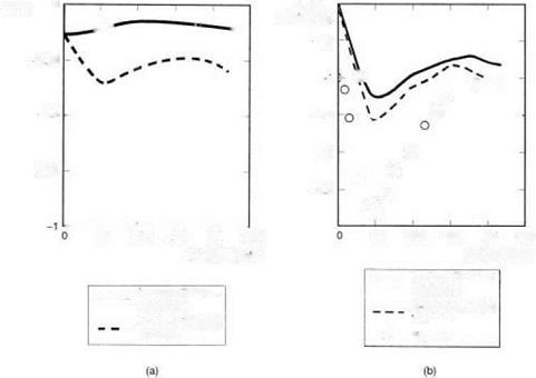
The assumption that the rotor thrust is normal to the disc throughout the flight envelope provides a common approximation in helicopter flight dynamics, effectively ignoring the many small contributions of the blade lift to the rotor in-plane forces given in the above equations. The approximation fails to model many effects however, particularly in lateral trims and dynamics. As an illustration, Fig. 3.11(a) shows a comparison of the rotor Y force in trim as a function of flight speed for the Helisim Bo105; the disc tilt approximation is grossly in error. The corresponding lateral cyclic comparison is shown in Fig. 3.11(b), indicating that the effect of the approximation on lateral trim is actually less significant. The disc tilt approximation is weakest in manoeuvres, particularly for teetering rotors or articulated rotors with small flapping hinge offsets, when the damping moment is dominated by the rotor lateral force rather than the hub moments. The most significant of the 3.90 series of equations is the first, the zeroth harmonic rotor thrust that appears in normalized form in eqn 3.90 itself. This simple equation is one of the most important in helicopter flight dynamics and we will return to it for more discussion when we explore the rotor downwash in the next section. To complete this rather lengthy derivation of the rotor forces and moments, we need to orient the hub-wind force components into shaft axes and derive the hub moments.
Using the transformation matrix derived in the Appendix, Section 3A.4, namely
![]() cos фw — sin фw
cos фw — sin фw
sin fw cos fw
we can write the X, Yforces in the shaft axes system aligned along the fuselage nominal plane of symmetry,
(3.103)

Fig. 3.11 Rotor side force and lateral cyclic variations in trimmed flight: (a) rotor side force
(Bo105); (b) lateral cyclic pitch (Bo105)
The rotor hub roll (L) and pitch (M) moments in shaft axes, due to the rotor stiffness effect, are simple linear functions of the flapping angles in MBCs and can be written in the form
Lh = —fKpPu (3.104)
Mh = —N-KpP1C (3.105)
The disc flap angles can be obtained from the corresponding hub-wind values by applying the transformation
The hub stiffness can be written in terms of the flap frequency ratio, i. e.,
K = ($ – 1) IpV2
 showing the relationship between hub moment and flap frequency (cf. eqn 3.32). The equivalent Kp for a hingeless rotor can be three to four times that for an articulated rotor, and it is this amplification, rather than any significant difference in the magnitude
of the flapping for the different rotor types, that produces the greater hub moments with hingeless rotors.
Rotor torque
The remaining moment produced by the rotor is the rotor torque and this produces a dominant component about the shaft axis, plus smaller components in pitch and roll due to the inclination of the disc to the plane normal to the shaft. Referring to Fig. 3.10, the torque moment, approximated by the yawing moment in the hub-wind axes, can be obtained by integrating the moments of the in-plane loads about the shaft axis
![]()

 (3.107)
We can neglect all the inertia terms except the accelerating torque caused by the rotor angular acceleration, hence reducing eqn 3.107 to the form,
![]()

![]() (3.108)
(3.108)
where IR is the moment of inertia of the rotor blades and hub about the shaft axis, plus any additional rotating components in the transmission system. Normalizing the torque equation gives
![]() , Nh______________ = 2Cq + Ц J^) й
, Nh______________ = 2Cq + Ц J^) й
Іp(йR)2nR3sa0 a0s Y
where
(3.110)
and the aerodynamic torque coefficient can be written as
we may express the rotor torque in the form
where the normalized aerodynamic loads are given by the expressions
г = U T в + UPUT, d = — U T (3.114)
ao
The three components of torque can then be written as
Expanding eqn 3.115 and making further approximations to neglect small terms leads to the final equation for rotor aerodynamic torque, comprising the induced terms formed from the product of force and velocity and the profile torque, namely
The rotor disc tilt relative to the shaft results in components of the torque in the roll and pitch directions. Once again, only one-per-rev roll and pitch moments in the rotating frame of reference will transform through as steady moments in the hub-wind axes. Neglecting the harmonics of rotor torque, we see that the hub moments can therefore be approximated by the orientation of the steady torque through the one-per-rev disc title
Lhq = —f fhc (3.117)
Mhq = QR flu (3.118)
We shall return to the discussion of hub forces and moments later in Section 3.4 and Chapter 4. We still have considerable modelling ground to cover however, not only for the different helicopter components, but also with the main rotor to cover the details of the ‘inner’ dynamic elements. First, we take a closer look at rotor inflow.
