Our heavyweight helicopter equal in the world does not have
In Rostov started production of the most load-lifting rotary-wing car The Russian holding «Helicopt[...]

Everything about aircrafts and helicopters. News and events in aviation worldwide. Civil, transportation, military helicopters and airplanes.

Everything about aircrafts and helicopters. News and events in aviation worldwide. Civil, transportation, military helicopters and airplanes.

Everything about aircrafts and helicopters. News and events in aviation worldwide. Civil, transportation, military helicopters and airplanes.

Everything about aircrafts and helicopters. News and events in aviation worldwide. Civil, transportation, military helicopters and airplanes.


In Chapter 1, a tip loss factor to account for the gradual falling off of the lift at the tip was used in the integration for hover thrust, and an approximate method was given for evaluating the tip loss factor as a function of the thrust coefficient and the number of blades. The same phenomenon exists in forward flight, but there is not yet any comparable method of evaluating the tip loss factor. Nevertheless, the need is recognized, so the closed-form equations are often derived using BR as the
upper limit of integration, and calculations are based on the value of В obtained with the hover equation or with an arbitrary constant such as 0.97. When the tip loss factor and
 |
|
|
![]()
![]()

These equations are more complicated looking than the corresponding equations without tip and root losses; but since В and x0 are constants, the resulting numerical equations, which are actually used for calculations, are no more complicated.
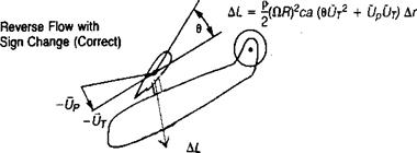
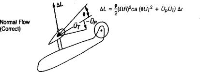
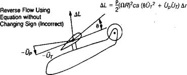
The integration process used so far has ignored the reverse-flow region, shown in Figure 3.14, by integrating around the azimuth from zero to 2n with no regard for the fact that in the reverse-flow region this method assigns the wrong sign to lift forces, as shown in Figure 3.50, and thus results in a calculated thrust value that is too high. For small tip speed ratios (less than about.25), the error is insignificant since both the size and the dynamic pressures in the reverse-flow region are small. At higher tip speed ratios, however, the error becomes more and more significant. The deficiency can be corrected during the integration by dividing the rotor into three regions, as shown in Figure 3.51, each with its separate limits of integration. Using this method, the thrust equation becomes:
![]()
|
|
|
|
|
|
|
|
![]()
![]()