Our heavyweight helicopter equal in the world does not have
In Rostov started production of the most load-lifting rotary-wing car The Russian holding «Helicopt[...]

Everything about aircrafts and helicopters. News and events in aviation worldwide. Civil, transportation, military helicopters and airplanes.

Everything about aircrafts and helicopters. News and events in aviation worldwide. Civil, transportation, military helicopters and airplanes.

Everything about aircrafts and helicopters. News and events in aviation worldwide. Civil, transportation, military helicopters and airplanes.

Everything about aircrafts and helicopters. News and events in aviation worldwide. Civil, transportation, military helicopters and airplanes.


Tip vortices (TiVs) exist on a finite wing because of the pressure difference between the upper and lower wing surface. The TiV establishes a circulatory motion over the wing surface and exerts great influence on the wing aerodynamics. Specifically, it increases the drag force. The total drag coefficient for a finite wing at subsonic speed can be written [44] as
C2
CD = CD, P + CD, F + —L, (2-22)
|
(b) |
|
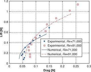
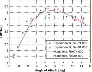
Figure 2.37. Numerical and experimental assessments of lift and drag over a MAV wing for different Reynolds numbers and AoAs [155]: (a) polar curve; (b) lift-to-drag ratio against the AoA. |
where CD, P is the drag coefficient due to pressure; CD, F is the drag coefficient due to skin friction; e is the span efficiency factor, which is less than 1; AR is the aspect ratio; and C2L/(neAR) = CDi is the induced drag coefficient due to the existence of TiVs. Equation (2-22) demonstrates that the induced drag varies as the square of the lift coefficient; at a high AoA, the induced drag can be a substantial portion of the total drag. Furthermore, it illustrates that, as AR is decreased, the induced drag increases. The MAV wing presented by Ifju et al. [17] has a low AR of 1.4; therefore, it is important to investigate TiV effects on the wing aerodynamics. In general, TiV effects are twofold: (i) TiV causes downwash that decreases the effective AoA and increases the drag force [44], and (ii) it forms a low-pressure region on the top surface of the wing, which provides additional lift force [159].
|
(b) |
|
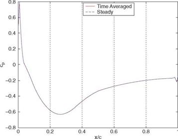
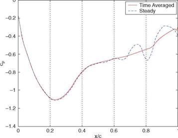
Figure 2.38. Comparisons of CP on a rigid wing at the root for steady and unsteady computations. (a) AoA = 6°; (b) AoA = 15°. From Lian and Shyy [158]. |
Figure 2.39 shows TiVs around the wing surface together with the streamlines at an AoA of 39° [160]. The vortical flow is usually associated with a low-pressure zone as shown in Figure 2.40. The pressure drop further strengthens the swirl by attracting more fluid toward the vortex core; meanwhile, the pressure decreases correspondingly in the vortex core. The low-pressure region created by the vortex generates additional lift. Toward the downstream, the pressure recovers to its ambient value, the swirling weakens, the diameter of the vortex core increases, and the vortex core loses its coherent structure.
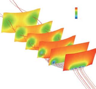 Figure 2.39. Streamlines and vortices for a rigid wing at the AoA = 39°. The vortical structures are shown on selected planes. From Lian et al. [163].
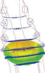 Figure 2.41 visualizes the evolution of the vortical structure with increasing AoA; it also presents the pressure distribution on the upper surface. At the AoA = 6°, TiVs are clearly visible even though they cover a small area and are of modest strength. The flow is attached to the upper surface and follows the chord direction. A low-pressure region is observed near the tip, caused by the vortical structure there.
Even though the flow on the upper surface near the root tends to separate, the flow remains attached in the outer portion of the wing; hence the lift still increases with the AoA until, of course, massive separation occurs on most of the upper surface. For low AR wings, TiVs make considerable contributions to the lift. This
10060 9810
Figure 2.40. Pressure distribution around the rigid wing in the cross-sections with streamlines at the AoA = 39°. From Lian et al. [163].
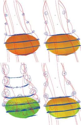
Figure 2.41. Evolution of flow pattern for rigid wing vs. AoAs. From left to right, top to bottom, 6°, 15°, 27°, and 51°. From Lian and Shyy [154]
 case is similar to that for delta wings. In his numerical study, Lian [161] observed that the low AR wing suffers less from separation. The wing is not subjected to sudden stall, but the lift coefficient levels off at very high AoAs. Torres and Mueller [162], in their experiments on low AR wings, found similar results. It should be noted that the analysis by Lian [161] included neither the fuselage nor the propeller.
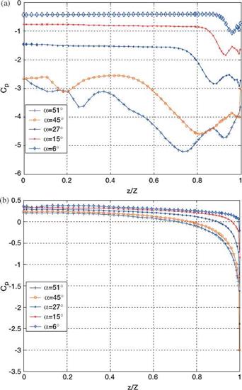
This pressure drop can be seen from Figure 2.42a, which plots the spanwise pressure coefficient on the upper-wing surface at x/c = 0.4. At the AoA = 6° the spanwise pressure is almost uniform on the upper-wing surface, and the TiV causes the pressure drop to occur at approximately 90 percent of the half-span from the root. Figure 2.42 is illustrative in regard to pressure distributions versus the vortical structures. Note that the illustrated pressure distributions are not indicative of the total level of the pressure force.
Vortices strengthen with the increase in the AoA. At the AoA = 27°, as shown in Figure 2.41, tip vortices develop a strong swirl motion while entraining the surrounding flow. The low-pressure area increases as the AoA becomes higher. In Figure 2.42a, the pressure drop moves along the spanwise direction toward the root and now occurs at 75 percent from the root.
At lower AoAs, the vortex core position shows a linear relation with the incidence. This relation disappears at higher AoAs when the flow is separated on the upper surface. For example, at the AoA = 45°, the flow is separated at the leading edge, and the low-pressure zone covers more than 40 percent of the wing surface, which helps maintain the increase in lift force. At the AoA = 51°, a considerable
|
Figure 2.42. Spanwise pressure coefficient distributions at x/c = 0.4 for rigid wing at different AoAs. (a) Pressure coefficient at upper surface; (b) pressure coefficient at lower surface. From Lian and Shyy [154]. |
spanwise velocity component is seen, and the flow is separated from most of the upper surface (see Fig. 2.41). The separation on the upper-wing surface decreases the lift, and stall occurs.
As observed earlier, the TiVs have an important effect on the aerodynamics of low AR wings. Again, one major effect is the increase in induced drag for low AR wings. Equation (2-22) shows that the smaller the AR, the larger the induced drag.