Our heavyweight helicopter equal in the world does not have
In Rostov started production of the most load-lifting rotary-wing car The Russian holding «Helicopt[...]

Everything about aircrafts and helicopters. News and events in aviation worldwide. Civil, transportation, military helicopters and airplanes.

Everything about aircrafts and helicopters. News and events in aviation worldwide. Civil, transportation, military helicopters and airplanes.

Everything about aircrafts and helicopters. News and events in aviation worldwide. Civil, transportation, military helicopters and airplanes.

Everything about aircrafts and helicopters. News and events in aviation worldwide. Civil, transportation, military helicopters and airplanes.


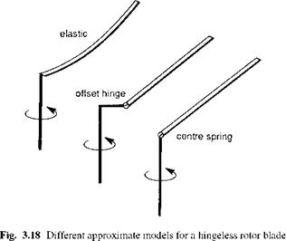
The centre-spring equivalent rotor, a rigid blade analogue for modelling all types of blade flap retention systems, was originally proposed by Sissingh (Ref. 3.32) and has considerable appeal because of the relatively simple expressions, particularly for hub moments, that result. However, even for moderately stiff hingeless rotors like those on the Lynx and Bo105, the blade shape is rather a gross approximation to the elastic deformation, and a more common approximation used to model such blades is the offset-hinge and spring analogue originally introduced by Young (Ref. 3.33). Figure 3.18 illustrates the comparison between the centre-spring, offset-hinge and spring and a typical first elastic mode shape. Young proposed a method for determining the values of offset-hinge and spring strength, the latter from the non-rotating natural flap frequency, which is then made up with the offset to match the rotating frequency. The ratio of offset to spring strength is not unique and other methods for establishing the mix have been proposed; for example, Bramwell (Ref. 3.34) derives an expression for the offset e in terms of the first elastic mode frequency ratio *1 in the form
with the spring strength in this case being zero. In Reichert’s method (Ref. 3.35), the offset hinge is located by extending the first mode tip tangent to meet the undeformed reference line. The first elastic mode frequency is then made up with the addition of a spring, which can have a negative stiffness. Approximate modelling options therefore range from the centre spring out to Bramwell’s limit with no spring. The questions
 |
that naturally arise are, first, whether these different options are equivalent or what are the important differences in the modelling of flapping motion and hub moments, and second, which is the most appropriate model for flight dynamics applications? We will try to address these questions in the following discussion.
We refer to the analysis of elastic blade flapping at the beginning of Chapter 3 and the series of equations from 3.8 to 3.16, developing the approximate expression for the hub flap moment due to rotor stiffness in the form
The third component due to the lift on the flap arm is O(e3) in the hover and will be neglected. The result given by eqn 3.195 indicates that the hub moment will be out of phase with blade flapping to the extent that any first harmonic aerodynamic load is out of phase with flap. Before examining this phase relationship in a little more detail, we need to explain the inconsistency between Young’s result above in eqn 3.184 and the correct expression given by eqn 3.195. To uncover the anomaly it is necessary to return to the primitive expression for the hub flap moment derived from bending theory (cf. eqn. 3.13):
![]() і 92w 2
і 92w 2
F(r, t) — m I -^2 + Q2w
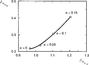
it is assumed that the flap frequency ratio kp and the blade Lock number remain constant throughout. These would normally be set using the corresponding values for the first elastic flap mode frequency and the modal inertia given by eqn 3.11. The values selected are otherwise arbitrary and uses of the offsetspring model in the literature are not consistent in this regard. We chose to draw our comparison for a moderately stiff rotor, with Yp = 1-2 and Sp = 0.2. Figure 3.20 shows a cross-plot of the flap control derivatives for values of offset e extending out to
|
Fig. 3.20 Cross-plot of rotor flap control derivatives |
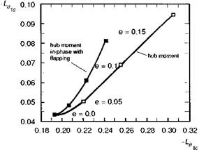
0.15. With e = 0, the flap frequency ratio is augmented entirely with the centre spring; at e = 0.15, the offset alone determines the augmented frequency ratio. The result shows that the rotor flapping changes in character as hinge offset is increased, with the flap/control phase angle decreasing from about 80° for the centre-spring configuration to about 70° with 15% offset. The corresponding roll and pitch hub moment derivatives are illustrated in Fig. 3.21 for the same case. Figure 3.21 shows that over the range of offset-hinge values considered, the primary control derivative increases by 50% while the cross-coupling derivative increases by over 100%. The second curve in Fig. 3.21 shows the variation of the hub moment in phase with the flapping. It can be seen that more than 50% of the change in the primary roll moment derivative is due to the aerodynamic moment from disc flapping in the longitudinal direction. These moments
|
Fig. 3.21 Cross-plot of roll control derivatives as a function of flap hinge offset |
could not be developed from just the first mode of an elastic blade and are a special feature of large offset-hinge rotors.
The results indicate that there is no simple equivalence between the centre-spring model and the offset-hinge model. Even with Young’s approximation, where the aerodynamic shear force at the hinge is neglected, the flapping is amplified as shown above. A degree of equivalence, at least for control moments, can be achieved by varying the blade inertia as the offset hinge is increased, hence increasing the effective Lock number, but the relationship is not obvious. Even so, the noticeable decrease in control phasing, coupled with the out-of-phase moments, gives rise to a dynamic behaviour which is not representative of the first elastic flap mode. On the other hand, the appeal of the centre-spring model is its simplicity, coupled with the preservation of the correct phasing between control and flapping and between flapping and hub moment. The major weakness of the centre-spring model is the crude approximation to the blade shape and corresponding tip deflection and velocity, aspects where the offset-hinge model is more representative.
The selection of parameters for the centre-spring model is relatively straightforward. In the case of hingeless or bearingless rotors, the spring strength and blade inertia are chosen to match the first elastic mode frequency ratio and modal inertia respectively. For articulated rotors, the spring strength is again selected to give the correct flap frequency ratio, but now the inertia is changed to match the rotor blade Lock number about the real offset flap hinge.
It needs to be remembered that the rigid blade models discussed above are only approximations to the motion of an elastic blade and specifically to the first cantilever flap mode. In reality, the blade responds by deforming in all of its modes, although the contribution of higher bending modes to the quasi-steady hub moments is usually assumed to be small enough to be neglected. As part of a study of hingeless rotors, Shupe (Refs 3.36 and 3.37) examined the effects of the second flap bending mode on flight dynamics. Because this mode often has a frequency close to three-per-rev, it can have a significant forced response, even at one-per-rev, and Shupe has argued that the inclusion of this effect is important at high speed. This brings us to the domain of aeroelasticity and we defer further discussion until Section 3.4, where we shall explore higher fidelity modelling issues in more detail.
Rotor blades need to lag and twist in addition to flap, and here we discuss briefly the potential contributions of these DoFs to helicopter flight dynamics.