Our heavyweight helicopter equal in the world does not have
In Rostov started production of the most load-lifting rotary-wing car The Russian holding «Helicopt[...]

Everything about aircrafts and helicopters. News and events in aviation worldwide. Civil, transportation, military helicopters and airplanes.

Everything about aircrafts and helicopters. News and events in aviation worldwide. Civil, transportation, military helicopters and airplanes.

Everything about aircrafts and helicopters. News and events in aviation worldwide. Civil, transportation, military helicopters and airplanes.

Everything about aircrafts and helicopters. News and events in aviation worldwide. Civil, transportation, military helicopters and airplanes.


The previous discussion has considered the rotor blades as rigid structurally but attached to the rotor hub by free hinges or flexures. In reality, the blades possess flexibility and can distort from the rigid straight shape adopted so far. The very significant tension under which the blades are subjected maintains an essentially straight shape but the complexities of the aerodynamic environment in which the blades operate will trigger elastic bending. How the blades do this is not appropriate for an introductory text. However, the blade natural modes are often used as a basis to define blade flexing and can be considered as separate for flap, lag and torsion (uncoupled modes) or when all three motions occur together (coupled modes). The torsion is of major importance for the KMax and Seasprite helicopters where this bending of the blades is used in rotor control – as previously discussed. The modal behaviour of the blades is closely involved in their design and, in the past, coupling of modes has been avoided. Modern blade development is now using blade modes, with their flap, lag and torsion components to enhance the aerodynamic performance. This use of favourable blade structural characteristics is known as ‘aeroelastic tailoring’.
4.1.2 Ground Resonance
The provision of individual blade lag hinges means that the rotor head will now become more complicated, will require extra maintenance and will add to the weight and drag of the rotor
head assembly. These are readily deduced; however, there is a dynamic implication of the blades moving in a lagwise sense. Firstly that the Coriolis effect connects the blade flapping and lagging motions. This can result in the two types of blade motion coupling together with implications for vibration and mechanical integrity. In addition, it is possible for the motion of the blades in lag to differ from blade to blade. If this should happen then the rotor, including blades, will have a CG which does not lie at the centre of the rotor. This will cause the generation of vibratory forces but also can cause a significant difficulty if the aircraft is sitting on the ground. The undercarriage will have an axial stiffness since it must compress on landing and therefore act as a spring. The stiffness of the undercarriage will allow the airframe itself to be able to vibrate at a frequency determined by the undercarriage stiffness and the appropriate moment of inertia of the airframe itself. We now have the situation of an oscillatory force being generated by the uneven blade lag motion, across the number of blades, acting on a system (the aircraft sitting on its undercarriage) which has its own natural frequencies. This is the classic combination which can result in a resonant condition if the forcing frequency closely approaches a natural frequency. In the case of a helicopter this can result in ground resonance which is a potentially devastating phenomenon and for which all new aircraft types are assessed before flight clearance is given.
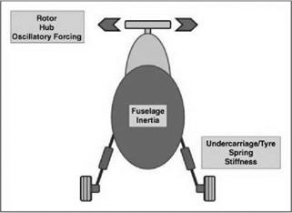
Figure 4.28 shows the basic features governing the natural frequency of the aircraft on the ground and the forcing derived from uneven blade lag motion. Should the forcing frequency at the rotor head be close to the natural frequency of the fuselage rocking on its undercarriage, a resonant condition can occur.
The undercarriage of a helicopter can be of many forms and Figure 4.28 shows an example. The strut consists of a spring and damper, and this is directly connected to the wheel and tyre unit. The latter has spring and damping properties due to the tyre inflation. The spring contributes to the fuselage frequency while the damping is present to suppress any potential ground resonance. The suppression of ground resonance is crucial and will be discussed later in this chapter.
|
|
|
Figure 4.29 Simple model of ground resonance 4.4.6.1 Simple Analysis of the Problem – Rotor Only |
The analysis of ground resonance can encompass a wide degree of complexity. The simplest model is to concentrate on the rotor alone and focus on the position of the CG. A further simplification is made where each blade is modelled by a concentrated mass joined to the lag hinge by a weightless rod. This is effectively viewing the individual blade mass centres.
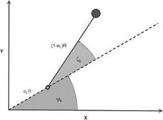
The rotor/blade layout is shown in Figure 4.29.
The figure shows a single blade (of index k) where the rotor head (and the appropriate lag hinge) itself is at an azimuth angle of Ck. The blade itself is placed in a leading (forward lag) position with angle zk.
The blade lag motion is then defined by:
Zk = Cocos IzCk (4-12)
which represents simple harmonic motion (SHM) of maximum amplitude z0 and circular frequency Af, relative to the rotor speed.
Substituting this lag behaviour into the position of the blade masses, the centre of mass of the N blades can be calculated. The analysis is relatively straightforward and produces a result which, if interpreted as a single mass, shows a motion which can be described as tracing the petals of a flower – see Figure 4.30.
While this explains the CG motion, it is not helpful, so rather than the motion of one specific mass, the result can be interpreted as the motion of two equal masses. The values of radial location and circular frequency is shown in the following table:
|
Mass 1 |
Mass 2 |
|
|
Mass |
mN |
mN |
|
Radial location |
rgf0 S 2N’S +1 |
rgf0 S 2N’S-1 |
|
Circular frequency |
(Af + 1)O |
(AC-1)Q |
![]() S = sin[(1z ± 1)p]
S = sin[(1z ± 1)p]
±! sin[(1c ± 1)n/N
The variation of the S terms with non-dimensional lag frequency is shown in Figure 4.31. The frequency which is greater than the rotor speed is known as progressive, indicating that the mass is rotating, relative to the rotor, in the direction of rotor rotation. The other is known as regressive since it moves against the rotor direction.
Figure 4.32 shows the result for the case of a normalized lag hinge offset of 0.1. The rotor has four blades and the two masses are circles at 2 and 8 o’clock. The overall rotor CG is the circle in between and, since the two masses are equal, it lies at their mid-point.