Our heavyweight helicopter equal in the world does not have
In Rostov started production of the most load-lifting rotary-wing car The Russian holding «Helicopt[...]

Everything about aircrafts and helicopters. News and events in aviation worldwide. Civil, transportation, military helicopters and airplanes.

Everything about aircrafts and helicopters. News and events in aviation worldwide. Civil, transportation, military helicopters and airplanes.

Everything about aircrafts and helicopters. News and events in aviation worldwide. Civil, transportation, military helicopters and airplanes.

Everything about aircrafts and helicopters. News and events in aviation worldwide. Civil, transportation, military helicopters and airplanes.


Rigid or elastic lead-lag blade motion attenuates the in-plane forces on the rotor. On articulated rotors, the rigid-blade lead-lag motion revolves about an offset hinge, necessary to enable the applied torque to rotate the rotor. On hingeless rotors, lead – lag takes the form of in-plane bending. Because the in-plane aerodynamic damping forces are low, it is usual to find mechanical dampers attached to the lead-lag hinge. Additional mechanical in-plane damping is even found on some hingeless rotors. A comprehensive discussion on the significance of lead-lag on blade stability and loads is provided by Johnson in Ref. 3.7. For most flight mechanics analysis, the presence of lead-lag motion contributes little to the overall response and stability of the helicopter. There is one aspect that is relevant and needs to be referred to, however. To aid the discussion, the coupled equations of flap/lead-lag motion are required; for the present purposes, we assume that the flap and lag blade inertias are equal and describe the
coupled motion in the simplified form:
![]()
![]() Ґ + kjp — 2ez = Mf
Ґ + kjp — 2ez = Mf
Z" + CzZ + k* Z + 2вв = Ml
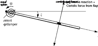
We assume that both the flap (в) and lead-lag (Z) motion can be approximated by the centre-spring equivalent model as illustrated in Figs 3.6 and 3.22. The direct inertial forces are balanced by restoring moments; in the case of the lag motion, the centrifugal stiffening works only with an offset lag hinge (or centre-spring emulation of centrifugal stiffness). If the lag hinge offset is ez, then the frequency is given by

 |
(3.212)
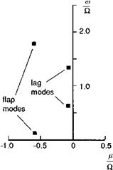
The natural lag frequency kz is typically about 0.25Й for articulated rotors; hingeless rotors can have subcritical (< Й, e. g., Lynx, Bo105) or supercritical (> Й, e. g., propellers) lag frequencies, but kz should be far removed from Й to reduce the amount of in-plane lag response to excitation. The flap and lag equations above have a similar form. We have included a mechanical viscous lag damper Cz for completeness. Mf and ML are the aerodynamic flap and lag moments. Flap and lag motions are coupled, dynamically through the Coriolis forces in eqns 3.210 and 3.211, and aerodynamically from the variations in rotor blade lift and drag forces. The Coriolis effects are caused by blade elements moving radially as the rotor flaps and lags. Because of the lower inherent damping in lag, the Coriolis moment tends to be more significant in the lag equation due to flap motion. In addition, the lag aerodynamic moment ML will be strongly influenced by in-plane lift forces caused by application of blade pitch and variations in induced inflow. The impact of these effects will be felt in the frequency range associated with the coupled rotor/fuselage motions. In terms of MBCs, the regressing and advancing lag modes will be located at (Й — kz) and (Й + kz) respectively. A typical layout of the uncoupled flap and lag modes is shown on the complex eigenvalue plane in Fig. 3.23. The flap modes are well damped and located far into the left plane. In contrast, the lag modes are often weakly damped, even with mechanical
|
Fig. 3.23 Flap and lag mode eigenvalues |
dampers, and are more susceptible to being driven unstable. The most common form of stability problem associated with the lag DoF is ground resonance, whereby the coupled rotor/fuselage/undercarriage system develops a form of ‘flutter’; the in-plane rotation of the rotor centre of mass resonates with the fuselage/undercarriage system.
Another potential problem, seemingly less well understood, arises through the coupling of rotor and fuselage motions in flight. Several references examined this topic in the early days of hingeless rotor development (Refs 3.38, 3.39), when the emphasis was on avoiding any hinges or bearings at the rotor hub to simplify the design and maintenance procedures. Control of rotor in-plane motion and loads through feedback of roll motion to cyclic pitch was postulated. This design feature has never been exploited, but the sensitivity of lag motion to attitude feedback control has emerged as a major consideration in the design of autostabilization systems. The problem is discussed in Ref. 3.6 and can be attributed to the combination of aerodynamic effects due to cyclic pitch and the powerful Coriolis moment in eqn 3.211. Both the regressing and advancing lag modes are at risk here. In Ref. 3.40, Curtiss discusses the physical origin of the couplings and shows an example where the advancing lag mode actually goes unstable at a relatively low value of gain in a roll rate to lateral cyclic feedback control system (-0.2°/°/s). In contrast, the roll regressing mode can be driven unstable at higher values of roll attitude feedback gain. The results of Ref. 3.40 and the later Bo105 study by Tischler (Ref. 3.41) give clear messages to the designers of autostabilizers and, particularly, high gain active control systems for helicopters. Designs will need to be evaluated with models that include the lead-lag dynamics before implementation on an aircraft. However, the modelling requirements for specific applications are likely to be considerably more complex than is implied by the simple analysis outlined above. Pitch-flap-lag couplings, nonlinear mechanical lag damping and pre-cone are examples of features of relatively small importance in themselves, but which can have a powerful effect on the form of the coupled rotor/fuselage modes.
Of course, one of the key driving mechanisms in the coupling process is the development of in-plane aerodynamic loads caused by blade pitch; any additional
dynamic blade twist and pitch effects will also contribute to the overall coupled motion, but blade pitch effects have such a profound first-order effect on flapping itself that it is in this context that they are now discussed.
Rotor blade pitch
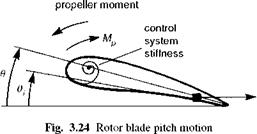
In previous analysis in this chapter the blade pitch angle was assumed to be prescribed at the pitch bearing in terms of the cyclic and collective applied through the swash plate. Later, in Section 3.4, the effects of blade elastic torsion are referred to, but there are aspects of rigid blade pitch motion that can be addressed prior to this. Consider a centrally hinged blade with a torsional spring to simulate control system stiffness, Ke, as shown in Fig. 3.24. For simplicity, we assume coincident hinges and centre of mass and elastic axis so that pitch-flap coupling is absent. The equation of motion for rigid blade pitch takes the form
![]()
 |
0ff + 0 — Mp + «2 9(
where the pitch natural frequency is given by
xQ — 1 + «2 (3.214)
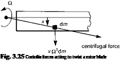 |
where Mp is the normalized applied moment and 0i is the applied blade pitch. The natural frequency for free pitch motion (i. e., with zero control system stiffness) is one – per-rev; on account of the so-called propeller moment contribution to the restoring moment. This effect is illustrated in Fig. 3.25 where mass elements along the chord line experience in-plane inertial moments due to small components of the large centrifugal force field. For rigid control systems, 0 — 0i. The control system stiffness is usually relatively high, giving values of me between 2 and 6 Й. In this range we usually find the first elastic torsion mode frequency, the response of which can dominate that of
the rigid blade component. A similar form to eqn 3.213 will apply to the first elastic mode, which will have a nearly linear variation along the blade radius. This aspect will be considered later in Section 3.4, but there are two aspects that are relevant to both rigid and elastic blade torsion which will be addressed here.
First, we consider the gyroscopic contribution to the applied moment Mp. Just as we found with flap motion earlier in this chapter, as the rotor shaft rotates under the action of pitch and roll moments, so the rotor blade will experience nose-up gyroscopic pitching moments of magnitude given by the expression
Mp(gym) = —2(p sin ft + q cos ft) (3.215)
The induced cyclic pitch response can then be written as
where P and q are the helicopter roll and pitch rates, with the bar signifying normalization by Й. For low blade torsional or swash plate stiffness, the magnitude of the gyroscopic pitch effects can therefore be significant. More than a degree of induced cyclic can occur with a soft torsional rotor rolling rapidly (Ref. 3.42).
The second aspect concerns the location of the pitch bearing relative to the flap and lag hinges. If the pitch application takes place outboard of the flap and lag hinges, then there is no kinematic coupling from pitch into the other rotor DoFs. However, with an inboard pitch bearing, the application of pitch causes in-plane motion with a flapped blade and out-of-plane motion for a lagged blade. The additional motion also results in an increased effective pitch inertia and hence reduced torsional frequency. These effects are most significant with hingeless rotors that have large effective hinge offsets. On the Lynx, the sequence of rotations is essentially flap/lag followed by pitch, while the reverse is the case for the Bo105 helicopter (Figs 3.26(a) and (b)). The arrangement of the flap and lag real or virtual hinges is also important for coupling of these motions into pitch. Reference 3.7 describes the various structural mechanisms that contribute to these couplings, noting that the case of matched flap and lag stiffness close to the blade root minimizes the induced torsional moments (e. g., Westland Lynx).
As already noted, any discussion of blade torsion would be deficient without consideration of blade elastic effects and we shall return to these briefly later. However, the number of parameters governing the dynamics is large and includes the location of the elastic axis relative to the mass axis and aerodynamic centre, the stiffness distribution and any pre-cone and twist. Introducing this degree of complexity into the structural dynamics also calls for a consistent approach to the blade section aerodynamics, including chordwise pitching moments and unsteady aerodynamics. These are all topics for further discussion in Section 3.4.
Before we proceed with detailing the modelling of the other rotorcraft components, there is one final rotor-related aerodynamic effect to be considered – ground effect.