Our heavyweight helicopter equal in the world does not have
In Rostov started production of the most load-lifting rotary-wing car The Russian holding «Helicopt[...]

Everything about aircrafts and helicopters. News and events in aviation worldwide. Civil, transportation, military helicopters and airplanes.

Everything about aircrafts and helicopters. News and events in aviation worldwide. Civil, transportation, military helicopters and airplanes.

Everything about aircrafts and helicopters. News and events in aviation worldwide. Civil, transportation, military helicopters and airplanes.

Everything about aircrafts and helicopters. News and events in aviation worldwide. Civil, transportation, military helicopters and airplanes.


For finding the velocity distribution around a given aerofoil, it is necessary to relate the angle of incidence a to the circulation Г around the aerofoil. This is done by applying the Joukowski hypothesis. In reality, the full Joukowski circulation required to bring the rear stagnation point to the trailing edge is not realized, because of the following:
• Air is a viscous fluid, and the flow near the trailing edge of an aerofoil is modified by the presence of the boundary layer and wake, caused by the viscosity.
• The zero thickness for the trailing edge, stipulated by the Joukowski hypothesis, is not possible in practice. Therefore, the trailing edge must be rounded to some degree of curvature. The finite thickness of the trailing edge owing to this rounding-off forces the rear stagnation point to deviate from the position given in the ideal case.
Therefore, if Г is the full Joukowski circulation (theoretical circulation), it can be assumed that the practical value of circulation is only кГ, where k is less than unity.
The velocity Vc, anywhere on the circle, given by Equation (4.11), is:
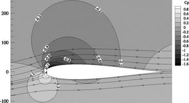
Knowing the distribution of Va/Vx, over the aerofoil, from Equation (4.17), the pressure coefficient around the aerofoil can be estimated.
Note that, with Equations (4.14), (4.15) and (4.17), the aerofoil shape, the velocity around it, and the Cp distribution around it can be computed, for the given values of b and e.
Example 4.5
For an aerofoil with b = 100 mm, e = 1/10 and (a) к = 1.0 and (b) к = 0.95, kept at a = 5°, determine the velocity and pressure around the transformed aerofoil.
Solution
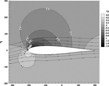
The aerofoil shape, the streamline pattern over the profile and the pressure coefficient variation around it, for the values b, e and a, listed in the problem were computed for Г = 1.0 and 0.95, with the routine given below. The results are given in Figures 4.18(a)-(d).
For Г = 1, the aerofoil shape, the streamlines and the pressure coefficient distribution around the aerofoil are shown in Figure 4.18(a). It is interesting to note that the flow leaving the aerofoil, at the trailing edge, is smooth and there is no wake, in accordance with Joukowski’s hypothesis. The Cp distribution
 |
300 —
-300 -200 -100 0 100 200
(a)
 |
200 –
-100
І
(b)
Figure 4.18 (a) Aerofoil shape, the streamline pattern over the profile and the pressure coefficient variation around
it, (b) Cp distribution over the aerofoil for Г = 1 and (c) the streamline pattern over the profile and the pressure coefficient variation around it, (d) Cp distribution over the aerofoil for Г = 0.95.
|
|
4
(c)
|
|
-400 -300 -200 -100 0 100 200 300
4
(d)
Figure 4.18 (Continued)
around the aerofoil, shown in Figure 4.18(b), clearly illustrates the higher pressure at the bottom and the lower pressure at the top of the profile, causing lift.
The streamlines and Cp variation around the aerofoil, for Г = 0.95 are shown in Figures 4.18(c) and 4.18(d), respectively. It is seen that, when Г is less than 1, the rear stagnation point is upstream of theAerofoil Characteristics
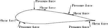
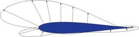
We saw that aerofoil is a streamlined body that would experience the largest value of lift-to-drag ratio, in a given flow, compared to any other body in the same flow. In other words, in a given flow the aerodynamic efficiency (L/D) of an aerofoil will be the maximum. When an aerofoil is exposed to a flow, due to the pressure acting normal to the body surface and the shear force, due to viscosity, acting tangential to the body surface, normal and tangential forces, respectively, would act on the aerofoil, as illustrated in Figure 4.19.
The pressure and shear forces can be integrated over the surface of the aerofoil to obtain the resultant aerodynamic force, Fa(j, which acts at the center of pressure (kcp) of the aerofoil.
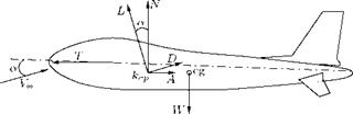
The forces acting on an aircraft in level flight are the lift L, drag D, thrust T and weight W, as shown in Figure 4.20.
In the xz-plane or pitch plane shown in Figure 4.20, the body-oriented components are the axial forces (A), which are the forces parallel to the aircraft axis, and the normal forces (N), which are
|
Figure 4.19 Normal and shear forces acting on an aerofoil in a flow field. |
|
Figure 4.20 Forces acting in the pitch (xz) plane on an aircraft. |
 |
perpendicular to the vehicle axis. As the aircraft travels in air, its motion is determined by its weight, the thrust produced by the engine, and the aerodynamic forces acting on the vehicle.
For a steady, unaccelerated level flight in a horizontal plane:
• The sum of the forces along the flight path is zero.
• The sum of the forces perpendicular to the flight path is zero.
When the angle of incidence a is small, the component of thrust parallel to the freestream flow direction is only slightly less than the thrust itself. Therefore, for equilibrium:
L = W T = D.
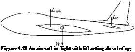
Let us consider the case where the lift generated by the wing-body configuration Lwb acts ahead of the center of gravity (cg), as shown in Figure 4.21.
The lift acting ahead of center of gravity will produce a nose-up (positive) moment about the center of gravity. The aircraft is said to be trimmed, when the sum of the moments about the cg is zero, that is:
Thus, a force from a control surface located aft of the cg, for example, the horizontal tail surface Lt is required to produce a nose-down (negative) pitching moment about the cg, which could balance the positive moment produced by Lwb. The tail surface producing Lt also produces a drag force which is known as the trim drag. The trim drag may vary from 0.5% to 5% of the total drag of the aircraft. It is essential to note that in addition to trim drag, the tail also produces drag due to the pressure and shear acting on its geometry, known as profile drag. Thus the trim drag is that associated with Lt generated to trim the vehicle.
In addition to the lift and drag acting in the pitch or xz-plane, there is a side force acting on the aircraft. The side force is the component of force in the direction perpendicular to both the lift and the drag. The side force acting towards the starboard (right) wing is referred to as positive.
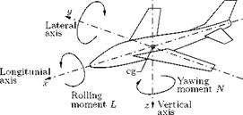
Usually the aerodynamic force will not act through the cg (which is also taken as the origin of the airplane’s axis system). The moment due to the resultant force acts at a distance from the origin may be divided into three components, referred to the airplane’s axes. The three moment components are the pitching moment M, the rolling moment L and the yawing moment N, as shown in Figure 4.22.
As illustrated in Figure 4.22: •
|
Pitching moment M
Figure 4.22 Illustration of pitching, rolling and yawing moments acting on an aircraft. |
• Rolling moment is the moment acting about the longitudinal axis (x-axis) of the aircraft. Rolling moment is generated by a differential lift generated by the ailerons, located closer to the wingtips. Rolling moment causing the right (starboard) wingtip to move downward is regarded as positive.
• Yawing moment is the moment acting about the vertical (z-axis) of the aircraft. Yawing moment tends to rotate the aircraft nose to the right is regarded positive.
4.15.1 Parameters Governing the Aerodynamic Forces
The primary parameters governing the magnitude of the aerodynamic forces and moments are the following:
• Geometry of the aerofoil.
• Angle of attack, namely the aircraft attitude in the pitch (xz) plane relative to the flight direction.
• Vehicle size.
• Freestream velocity.
• Freestream flow density.
• Reynolds number (viscous effects).
• Mach number (compressibility effects).