Our heavyweight helicopter equal in the world does not have
In Rostov started production of the most load-lifting rotary-wing car The Russian holding «Helicopt[...]

Everything about aircrafts and helicopters. News and events in aviation worldwide. Civil, transportation, military helicopters and airplanes.

Everything about aircrafts and helicopters. News and events in aviation worldwide. Civil, transportation, military helicopters and airplanes.

Everything about aircrafts and helicopters. News and events in aviation worldwide. Civil, transportation, military helicopters and airplanes.

Everything about aircrafts and helicopters. News and events in aviation worldwide. Civil, transportation, military helicopters and airplanes.


This chapter highlighted the rigid fixed-wing aerodynamics at the low Reynolds number range between 103 and 106. As the Reynolds number drops from 106 to 104 or lower, the lift-to-drag ratio of an airfoil substantially decreases. A thinner airfoil with modest camber is preferable for low Reynolds number flyers because it generates better lift-to-drag ratio and power efficiency compared to conventional airfoils.
At the Reynolds number around 104, the laminar-to-turbulent transition and LSB play important roles in determining airfoil performance. In this flow regime, the lift-to-drag polar exhibits zigzag characteristics that are due to the formation and burst of the LSB. Because of the effect of transition, the wing performance is expected to be sensitive to the free-stream turbulence intensity and wind gust. For low Reynolds number flight, drastically unconventional wing shapes may be beneficial. For example, a corrugated wing is less sensitive to the variation in Reynolds number, and it can provide a more favorable lift than a non-corrugated wing because the viscous effect substantially modifies the effective airfoil shape. In essence, protruding corrugation corners act as boundary-layer trips to promote the transition of the boundary layer from laminar to turbulent while remaining “attached” to the envelope profile of the high-speed streamlines; however, a corrugated wing can also experience higher drag coefficients compared with those of the smooth-surfaced airfoil.
A downwash movement induced by a TiV reduces the effective AoA of a wing. For a low AR and low Reynolds number wing, the induced drag by the TiV substantially affects its aerodynamic performance. The TiVs affect not only lift and drag generation but also potentially flight stability. Moreover, wind gust is a prominent factor in low Reynolds number flyers. The low Reynolds number aerodynamics often exhibits hysteresis in a gusty environment. The transition position varies with the local Reynolds number, and depending on the flow parameters, either drag or thrust can be generated from the unsteady aerodynamics.
As we have explored in the previous chapters, flying animals flap wings to create lift and thrust, as well as to perform remarkable maneuvers with rapid accelerations and decelerations. Insects, bats, and birds provide illuminating examples of using unsteady aerodynamics that can guide the design of MAVs.
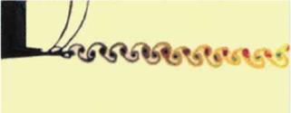
The first experimental work confirming the possibility of thrust generation on the unsteadily moving wing was conducted by Katzmayr in 1922 [168]. He investigated a fixed wing placed into an oscillating flow field. His studies validated the Knoller-Betz hypothesis [169] [170]. Both Knoller and Betz observed that the vertical motion of a flapping wing creates an effective AoA, generating an aerodynamic force with both lift and thrust components. Polonskiy [171] and Bratt [172] performed detailed visualizations of the large-scale vortex structures shed from harmonically plunging foils in a uniform flow and observed the characteristics of the vortex structures behind the airfoils. These experimental observations confirmed the Karman-Burgers thrust – generation hypothesis (i. e., the formation of a reverse Karman vortex street). In their experiments Polonskiy [171] and Jones et al. [173] showed the existence of different types of large-eddy structures generated by oscillating wings, as well as the vortex structures that are shed at an angle to the free-stream. Other researchers [174]- [178] studied the 2D flow structure behind oscillating foils and thrust generation, confirming that, depending on the parametric conditions, the wake structure can change from simple sinusoidal perturbations to two or four large-scale eddies. These typical flow structures were experimentally captured in flow visualization by Lai and Platzer [179]. Figure 3.1 shows the typical Karman vortex street behind a stationary NACA 0012, in which clockwise rotating vortices are shed from the upper surface and counterclockwise rotating vortices are shed from the lower surface; Figure 3.2a shows two pairs of vortices shed from the trailing edge of a NACA 0012 per plunge cycle, whereas Figures 3.2b and c show a single pair with a reverse Karman vortex street pattern. When an airfoil plunges at zero angle of incidence without an incoming flow, as shown in Figure 3.3a, a jet is produced by the flapping airfoil, and the streamwise velocity downstream of the airfoil is greater than the peak plunge velocity [180]. The jet appears to be biased toward the half-plane above the airfoil. This phenomenon was also observed by Jones et al. [181]. It occurs because, as soon as St exceeds approximately 0.8, the vortices shed from the trailing edge come too close together and start to interact with each other. In another experiment with a circular cylinder,
|
Figure 3.1. Vortical structure behind a stationary NACA 0012 airfoil for a free-stream velocity of 0.2 m/s [179]. |
the jet flow is not observed (see Fig. 3.3b). Therefore, it seems that the jet flow is caused by the detailed geometry such as curvature and asymmetry of the solid object. In another study, Taneda investigated the influence of traveling-wave characteristics associated with a flexible plate [182]. He revealed that the turbulence in the boundary layer is suppressed when the speed of propagation of the traveling wave exceeds that of the uniform incoming flow.
|
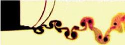
(a) ha = 0.0125 (St = 0.098) |
|
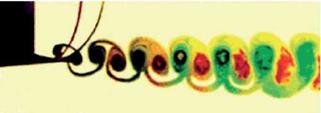
(b) ha = 0.025 (St = 0.196) |
|
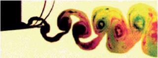
(c) ha = 0.05 (St = 0.392) Figure 3.2. Vortex patterns for a NACA 0012 airfoil oscillated in plunge for a free-stream velocity of approximately 0.2 m/s, a frequency of f = 2.5 Hz, Re = 2.1 x 10⁴, and various amplitudes of oscillation [179]. |
 |
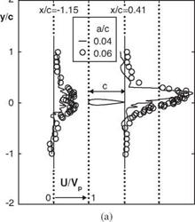 |
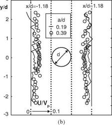
Figure 3.3. Non-dimensional mean streamwise velocity profiles generated by a (a) plunging airfoil, and (b) plunging cylinder at f = 5 Hz [180].
The interaction of large-scale eddies with oscillating wings has been noticed for many years in the context of observing fish bodies that generate large-scale eddies [183]. Gopalkrishnan et al. [184] and Streitlien and Triantafyllou [185] identified three types of interactions of the harmonically oscillating wing with vortices in the wake: (i) optimal interaction of the new vortices with the vortices shed by the wing, resulting in the generation of more powerful vortices in the reverse Karman vortex street; (ii) destructive interaction of new vortices with those shed by the wing, resulting in the generation of weaker vortices in the reverse Karman street; and (iii) interaction of vortex pairs with opposite sign shed from the wing, leading to the generation of a wide wake composed of vortex pairs that are shed at an angle to the free-stream. Furthermore, Triantafyllou et al. [186] observed that the interaction between large-scale vortex structures generated by the fish body and vortex structures of the fin are important factors in determining the performance of swimming. In the “normal” case, the initial pair of large-scale vortices is generated by the body. Then the body-generated vorticity is redirected by the fin and interacts with the fin-generated vorticity to produce the vortex pair, which is “accurately controlled” by the fish. The timing of vortex formation, propagation, and its instantaneous position are critical for efficient maneuvering and acceleration. Thus the control of vortex generation plays an important role in achieving high locomotion efficiency. In summary, depending on the features of the interactions between airfoil movement and the associated flow structure, either thrust or drag generation can be observed.
Another experiment discovered the delay of the leading-edge flow separation in unsteady motion. Devin et al. [187] indicated that, for a rigid wing with an AR of from 1 to 4 and a NACA 0012 section, no separation is observed up to the instantaneous AoA of 45°; in contrast, separation normally occurs at AoA = 15° (Re = 105) in the steady case. Moreover, investigations [188]-[190] have found that the stall does not come instantly when a wing is rapidly pitched beyond the static stall angle. Figure 3.4
 |
 |
depicts the evolution of the flow structures in dynamic stall for a rapidly pitching NACA 0012 airfoil [191]. The reverse flow affects the pressure distribution (point b in Fig. 3.4) after the wing rapidly exceeds the static stall angle (point a in Fig. 3.4). This reversal progresses up on the airfoil upper surface and forms a vortex. This vortex initially appears near the leading edge of the airfoil (point c in Fig. 3.4),
enlarges, and then moves down the airfoil. The pitching moment reaches its negative peak, and then both lift and pitching momentum start to drop dramatically (points d and f in Fig. 3.4), producing the phenomenon known as dynamic stall. As the AoA decreases, the vortex moves into the wake and a fully separated flow develops on the airfoil. At the time instant when the AoA reaches its minimum AoA, lift has not reached its minimum value, which indicates that the dynamic stall process forms a hysteresis loop. Figure 3.4 shows such characteristics for the development of lift and pitching momentum. The amplitude and the shape of the hysteresis loop depend on the oscillation amplitude, mean AoA, and reduced frequency.
Jones and Platzer [192] developed and experimentally tested a flapping wing MAV. In their MAV configuration, lift is generated by a fixed forewing while thrust is produced by two flapping hindwings (see Fig. 1.15c) based on the thrust generation mechanisms discussed earlier. It is interesting to note that they also showed different possibilities of flapping airfoil usage, such as the reduction or suppression of flow separation behind blunt or cusped airfoil trailing edges. Willis et al. [193] and Persson et al. [194] presented a computational framework to design and analyze flapping MAV flight.
Moreover, pioneering works on flapping wing aerodynamics of biological flyers and swimmers have been published by Lighthill [40] and Weis-Fogh [68]. Further efforts, both in experiments and simulations, are documented by Ellington [65], Katz and Plotkin [195], DeLaurier [196], Smith [197], Vest and Katz [198], Ellington et al. [199], Liu and Kawachi [200], Dickinson et al. [201], Jones and Platzer [202] [203], and Wang [204], to name a few. A review of the characteristics of both flapping wings and fixed-wings has been given by Shyy et al. [205]. Recently, the number of publications related to flapping wing aerodynamics has greatly increased, indicating rapidly growing interest in this research field. Summaries of the recent efforts can be found in the books related to the aerodynamics of biological flyers [28] [206] and MAVs [36] [ 207].Valuable sources of information include special issues of the AIAA Journal (Vol. 46, 2008) and Experiments in Fluids (Vol. 46, No. 5, 2009), as well as numerous articles in the Encyclopedia of Aerospace Engineering (2010).
Conclusions and observations commonly made in these studies are that aerodynamic phenomena associated with biological flights prominently feature unsteady motions, characterized by large-scale vortex structures, 3D flapping kinematics, and flexible wing structures. Furthermore, knowledge gained from studying biological flight shows that the steady-state aerodynamic theory can be seriously challenged as an explanation for the lift needed to keep biological flyers aloft [26] [65] [199].
The quasi-steady theories are constructed based on the instantaneous velocity, wing geometry, and AoA while employing the steady-state aerodynamic model. By neglecting the flow history, the quasi-steady approach greatly simplifies the time – dependent problem by converting it to a sequence of independent, steady-state problems, and so it has been frequently used in interpreting biological flight characteristics [4] [43] [60] [68] [80] [208]-[210]. For example, this approach has been used to estimate the mechanical power requirements of hummingbirds [211] and bumblebees [212]. However, based on the theoretical analyses [213] and experimental measurements of tethered insects [214] [215], it has been found that the quasisteady model is insufficient to predict the lift needed to support the weight of the insect body. In contrast, two studies [216] [ 217] involving a dynamically scaled, rigidwinged, flapping robotic flyer flapping in mineral oil suggest that the quasi-steady 2D blade element models can yield satisfactory agreement with the experimental measurement of aerodynamic forces. Further discussions and assessments regarding the quasi-steady aerodynamic model are presented in Section 3.6.
In this chapter we present various issues related to the aerodynamics of flapping flight of rigid wings. First, we discuss the scaling of flapping wing flight in terms of reduced frequency, Reynolds number, and Strouhal number. These nondimensional parameters are important for investigating fluid physics of both rigid and flexible wings; discussion of flexible wing structures and aeroelasticity is presented in Chapter 4. Then, we discuss the main unsteady lift-enhancing aerodynamic mechanisms associated with flapping wings, including delayed stall of leading-edge vortex (LEV); rapid pitch-up; wake capturing; interactions between LEV, trailing-edge vortex (TEV), and tip vortex (TiV); and clap-and-fling mechanisms. Subsequently, we look at the fluid physics in two different Reynolds number regimes in more detail. For both Reynolds number regimes, we investigate the effects of wing kinematics on the resulting flow field and aerodynamics.
For the Reynolds number regime of O(102), we compare the aerodynamics of the 3D hovering wing to its 2D counterpart and discuss the effects of free-stream fluctuations on aerodynamic performance. In this Reynolds number regime, intriguing fluid dynamics phenomena are observed for a free-to-move vertically plunging rigid wing [218]. The vertical motion of the wing is imposed with sinusoidal kinematics, whereas the wing is free to move in its horizontal directions. When the plunging frequencies are below a threshold value (i. e., Re (= p fhac/p) < 3.9 x 10²), the wing remains stationary in the horizontal plane, and the wakes shed in the flow form a symmetric structure. For the frequencies above this threshold value, such that Re > 3.9 x 10², the symmetry of the wake breaks, resulting in an inverted von Karman vortex street that is indicative of propulsion: the flapper moves forward. When the rigid wing is replaced with a flexible plate with the same geometry but with lower elastic modulus, the resulting forward speed is significantly greater than that of the rigid wing [219]. For more details we refer the reader to the literature (e. g., [218] [220] [221] for rigid wings and [219] [222] [223] for passively pitching wings).
For the Reynolds number regime of O(104) we focus on the effects of airfoil shapes on pitching and plunging wings in forward flight. Furthermore, we review approximate analysis for non-stationary airfoil aerodynamics and discuss several quasi-steady models. Finally, we highlight fluid physics associated with biological flapping flyer-like models, including the flyer’s scale effects on resulting flow structures such as LEVs and spanwise flow.