Our heavyweight helicopter equal in the world does not have
In Rostov started production of the most load-lifting rotary-wing car The Russian holding «Helicopt[...]

Everything about aircrafts and helicopters. News and events in aviation worldwide. Civil, transportation, military helicopters and airplanes.

Everything about aircrafts and helicopters. News and events in aviation worldwide. Civil, transportation, military helicopters and airplanes.

Everything about aircrafts and helicopters. News and events in aviation worldwide. Civil, transportation, military helicopters and airplanes.

Everything about aircrafts and helicopters. News and events in aviation worldwide. Civil, transportation, military helicopters and airplanes.


A 6DOF flight simulator is required for a fighter aircraft development program to carry out full nonlinear flight dynamics simulation and for aiding the design of flight – control laws, via iterative validation of these laws. Also, it is required for evaluation of the control laws during the design process and even during and after the flight tests of the prototype aircraft. A simulator would consist of (1) visual system hardware—projector, screen, instrument panel/virtual instruments, (2) visual software—terrain, runway near airfield, clouds/rains visuals, (3) cockpit with throttle handle, pitch-roll control stick, rudder pedals, and the pilot’s seat, (4) computers mainly PCs, to solve flight dynamics equations, atmospheric models, and execution of software to link various subsystems/models, and (5) data acquisition system.
The generation of visual imagery is very crucial to obtain good fidelity of the simulator [4]. Video films/CCTV (close circuit TV) camera can be used for visual scene creation. The CCTV camera captures the terrain view (from its physical model) and the view is projected on the screen of the simulator. Computer generated imagery (CGI) is used to generate the required imagery in real time. This is the most widely used system for visual generation/simulation.
The steps for generating visual imagery are (1) definition of objects—runway, roads, trees, buildings, clouds, terrain, and lights—this defines a viewing volume, (2) creating the objects with appropriate texture and level of detailing (LOD) required
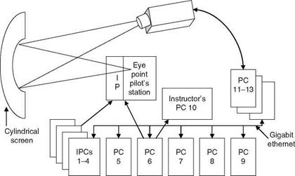
and storage of these data/information, (3) creating the visuals by appropriate definitions of all the required/desired objects with respect to some reference coordinates system, and (4) linking of the virtual world to the dynamics of the flight by appropriate timing and coordinate transformation and projecting the visuals on to 2D screen form the pilot’s eye point. This is called a rendering-projecting-timing cycle for visual simulation with delays of less than 100 ms and a screen refresh rate of about 60 Hz. If the monitor screen has to display the graphic picture of 1280 x 1024 pixels with depth complexity 4 units, then at the rate of 60 Hz, the pixel transfer rate needed is 4 x 60 x 1024 x 1280 = 312 Mpixels/s [4]. This can be provided by four raster managers with 80 Mpixels/s. The raster-type computer display is generally used for this purpose. It draws the images by dots or pixels and each pixel is represented by a sequence of bits. The map of one screen represented in the form of bits is termed as bitmap and the location of the corresponding bit in the computer memory is called the frame buffer. A display controller passes the contents of the frame buffer to the screen at the rate of 30 Hz to avoid flicker. Interestingly, many powerful visual software modules are available nowadays, but could be very expensive. Development of such SW could be very timeconsuming and involves a lot of effort. A good picture of interconnectivity of various HW/SW modules of a PC-based flight simulator is given in Figure 6.8. The pilot’s eye point is rigidly linked to the aircraft altitudes and positions in relation to the Earth. The variables that change during flight progression update the visuals (visual scenery) as observed by the pilot.
|
FIGURE 6.8 Schematic outline of a PC-based flight simulator. (IPCs 1-4: instrumentation data/simulation; PC 5: flight model, autopilot; PC 6: data acquisition system; PC 7: avionics simulation; PC 8: data storage/feel system simulation; PC 9: aural simulation; PC 10: instructor’s station; PC 11-13: visual system/SW; IP: instrument panel/displays.) |