
Our heavyweight helicopter equal in the world does not have
In Rostov started production of the most load-lifting rotary-wing car The Russian holding «Helicopt[...]

Everything about aircrafts and helicopters. News and events in aviation worldwide. Civil, transportation, military helicopters and airplanes.

Everything about aircrafts and helicopters. News and events in aviation worldwide. Civil, transportation, military helicopters and airplanes.

Everything about aircrafts and helicopters. News and events in aviation worldwide. Civil, transportation, military helicopters and airplanes.

Everything about aircrafts and helicopters. News and events in aviation worldwide. Civil, transportation, military helicopters and airplanes.


One of the main reasons for the use of the hot wire anemometer in fluid mechanics is its ability to follow turbulent fluctuations in speed. In the CCA, the key parameter is the heat capacity of the wire which opposes temperature changes; at increasing frequency of speed fluctuations the sensor follows the change of velocity with an increasing delay and the amplitude of the oscillations in output will become smaller compared with that in input. This behavior can be expressed quantitatively by evaluating the frequency response of the CCA.
From Equation (3.2), taking into account Equation (3.7):
– IіRw + (a + b4U)Rw ~ Ra = 0 aRa dt w V > aRa
The differential equation that links the resistance of the wire with time is linear of the first order and it follows that in response to a sudden increase in speed (Figure 3.10) the resistance decreases with the law
Rw = Rw1 – DRw(1 – e-tTw) (3.10)
Response of the resistance of the probe of a CCA to a step increase in the speed of the stream
 Velocity
▲
иг
 |
Ui ——-
where Rw1 is the initial resistance and Rw2 = Rw1 – DRw is the resistance that the wire would reach asymptotically for t = ^. tw is the time constant of the wire
![]()
![]()
![]() (3.11)
(3.11)
that represents the time that resistance takes to reach the value
Rw = Rw1 – DRw (1 – ej = Rw1 – 0.63DR
or, similarly to what has been said for the time constant of a U-tube manometer (cf. Section 1.2.1.2), the time it would take to reach the new equilibrium value if the rate of change were the initial one. As shown in Equation (3.11), the time constant, which is a measure of the change of wire resistance (temperature), increases with the overheating ratio and with the decrease in speed. For the reference probe tw = 0.6 ms.
The time constant can be associated with a cut-off frequency or frequency limit:
which is also the bandwidth of the frequency of the sensor (for the reference probe fc = 300 Hz).
 |
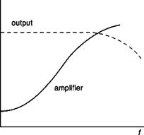 |
Frequency response of sensor, amplifier and CCA
Dryden in 1929 showed that if applying to the sensor a speed variable with a certain frequency, f, the amplitude of the output signal from the sensor is not equal to that which would occur in the steady case but decreases in the ratio (Figure 3.11)
![]() A = 1
A = 1
A = 1 + (//f)2
and that the output signal has a delay of phase with respect to the input signal equal to
![]() Da = tg – (ff)
Da = tg – (ff)
From Equations (3.13) and (3.14) it can be seen that the frequency limit can also be defined as the frequency at which the reduction in amplitude of the power is equal to 1/2 (-3dB) and the phase delay is 45°.
In order to offset the effect of reducing the amplitude of the signal, the amplifier connected with the sensor should have a gain variable with frequency (Figure 3.11) with a reverse law with respect to Equation (3.13); of course also the amplifier has its own inertia for which the best that can be obtained is an extension of the bandwidth of the wire sensor – amplifier system from 300 Hz to a few kHz.


