Our heavyweight helicopter equal in the world does not have
In Rostov started production of the most load-lifting rotary-wing car The Russian holding «Helicopt[...]

Everything about aircrafts and helicopters. News and events in aviation worldwide. Civil, transportation, military helicopters and airplanes.

Everything about aircrafts and helicopters. News and events in aviation worldwide. Civil, transportation, military helicopters and airplanes.

Everything about aircrafts and helicopters. News and events in aviation worldwide. Civil, transportation, military helicopters and airplanes.

Everything about aircrafts and helicopters. News and events in aviation worldwide. Civil, transportation, military helicopters and airplanes.


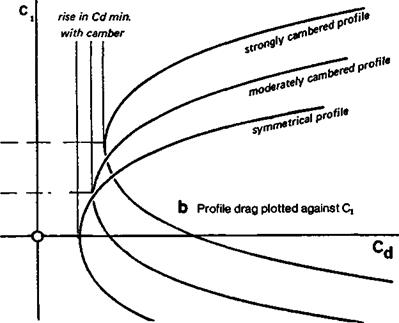
For most of the time the landing condition is not particularly significant for models. The reason that slow flying models should have well cambered profiles, and fast models less cambered ones, is entirely a matter of drag reduction. The influence of camber on drag of an aerofoil is shown in Figure 7.7. Compared with symmetrical wings, the cambered surface has a slightly higher minimum profile drag, but far more significant is the movement of the drag curve as the camber increases. The angle of attack in Figure 7.7a is the aerodynamic angle, measured from the absolute zero. In some earlier wind tunnel testing, the drag graph was plotted against angle of attack measured geometrically. The rightward shift of the curve was to some extent concealed, since it was easy to overlook the /е/1-ward shift of the lift curve with camber. In modem practice, the drag curve is always plotted against ci directly (Fig. 7.7b) and the true relationship is then clear. (The angle of attack has to be found by cross plotting to the ci curve.) In practice the modeller seldom knows at what angle of attack the wing operates, since the model’s attitude changes frequently. Downwash in any case induces a different angle from the simple geometric expectation, but the wing Cl is controlled by trimming. It is of utmost importance that the camber should be correctly chosen to give minimum drag at the particular Cl at which the model is flying. This is particularly vital for high speed models
|
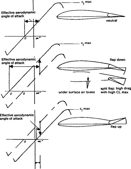
Fig. 7.6 Hinged control surfaces Geometrically the angle of attack is always measured from the chord or other reference line with zero control deflection. The aerodynamic effects are as shown when controls are deflected.
|
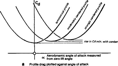
where profile drag is such a large item in the drag budget; it is less important, though still significant, for slow flying models.
Some pylon racers have been built with the wrong camber As Figure 7.7 shows, there is one value of q at which profile drag is a minimum for each value of camber. If a symmetrical wing is trimmed to fly at a positive angle of attack, as it must be for flight in equilibrium, it will operate at some point on the drag curve above the minimum. On the other hand, if a cambered profile is trimmed at too low a q, it too will produce too much drag.
|
|
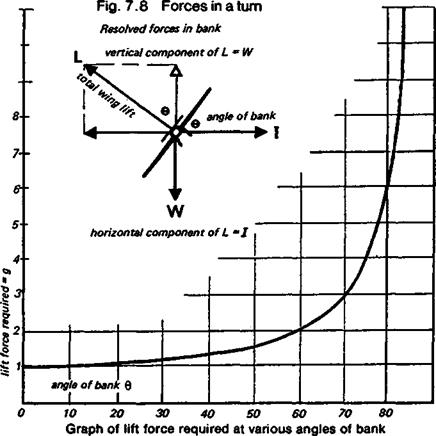
With the help of a little arithmetic it is possible to determine the best camber for any speed model, if its actual speed, or the speed hoped for in the design stages, is known. This is explained in Appendix 1. At maximum speed in level flight very little camber is required, with a light model, but racing models spend comparatively little of their flying time in equilibrium, they not only fly straight and level, but have to bank round the pylons. This, as shown in Figure 7.8, increases the ci at which the profile operates, to generate the extra lift force to counteract inertia in the turn. How much extra force is needed depends entirely on the angle of bank; a bank angle of 60 degrees doubles the effective lift required, a further eleven or twelve degrees triples the load, and banking angles of 80 degrees or more send the ‘g’ forces rocketing. In such steep turns the wing is forced to a higher angle of attack, and with the thin slightly cambered profiles commonly used, this may cause a considerable increase in drag or even a stall The extra drag slows the model down, reducing the average speed for the lap in any case. It may be much more significant than that The reduction of V in the lift formula means that the Cl must go still higher. With a thin, slightly cambered wing, this too can produce a stall and the race ends immediately for that model. The model needs either a wing which produces low drag over a range of ci values, such as one of the laminar flow aerofoils discussed in Chapter 9, or it needs a variable camber wing, i. e. flaps which can be lowered slightly at the turns; not so much to increase Cl, but to shift the drag curve to give minimum profile drag at the higher angle of attack in the turn.
For duration models and gliders which are trimmed to fly at Cl’VCd maximum, it is necessary to reduce profile drag as far as possible by moving the drag curve to a high ci position, accomplished by cambering more. This also raises the ci maximum, enabling the model to be trimmed for slow flight The ideal camber is harder to determine than for a speed model, since the calculation method requires detailed wind tunnel test results for the profile used, and these are rarely available. Given such figures, like those presented in Appendix 2, the value of Cl1 5/Cd, duly corrected for the aspect ratio and with allowance for parasite drag, may be calculated by arithmetical methods and plotted on a graph to find the best operating Cl and check the camber again. The model may then be trimmed to fly at the airspeed appropriate to the Cl – Some examples of the type of calculation required are given in Appendix 2.