Our heavyweight helicopter equal in the world does not have
In Rostov started production of the most load-lifting rotary-wing car The Russian holding «Helicopt[...]

Everything about aircrafts and helicopters. News and events in aviation worldwide. Civil, transportation, military helicopters and airplanes.

Everything about aircrafts and helicopters. News and events in aviation worldwide. Civil, transportation, military helicopters and airplanes.

Everything about aircrafts and helicopters. News and events in aviation worldwide. Civil, transportation, military helicopters and airplanes.

Everything about aircrafts and helicopters. News and events in aviation worldwide. Civil, transportation, military helicopters and airplanes.


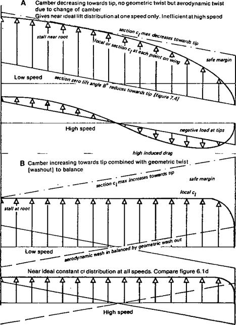
By varying the camber along the span, the stalling characteristics may be controlled. If the camber is reduced towards the tips, with no geometric twist (i. e. the true chord line of each rib is at the same angle to the building board or datum line), the wing will have an aerodynamic washout because the aerodynamic zero angle of attack at each point will differ. Assuming a nearly elliptical planform, the wing roots, because of the greater camber there, will reach their stalling angle before the tips. This is good in the sense that it prevents tip stalling. At high speeds, however, when the roots are still lifting, the tips will already be close to their aerodynamic zero. The lift distribution will not be elliptical, and at some speed the tips will begin to bend downwards like a wing with marked geometrical washout (Fig. 7.5). To restore elliptical lift distribution, the tips should really be twisted the other way (wash-in), which will unfortunately cause tip stalling because the less – cambered profile has a lower ci maximum. Many models have been built with reduced camber at the tips plus a few degrees of washout. This combines both aerodynamic and geometric washout; the total effect may be as much as six or seven degrees of aerodynamic twist The tip stall is controlled, but the efficiency suffers.
If, instead of camber decreasing at the tips, it is increased, or decreased at the roots, the tips will tend to stall first which is highly undesirable. However, if the aerodynamic twist or ‘wash-in’ caused by the increased tip camber is counteracted by an equal geometric twist or washout in the opposite direction, the result is excellent If, for example, the difference in absolute zero of the aerofoil at the wing root and that at the tip is two degrees, with the more cambered form at the tip the geometric twist should be two degrees washout or, to be on the safe side, a little more. The whole wing then reaches its aerodynamic zero at the
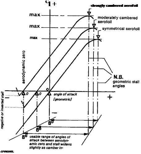 |
same angle, and the ci from tip to root is nearly constant The lift load thus approaches as closely as possible to the ideal (assuming the planform of the wing is a good approximation to an ellipse). There is no tip stall, because the more cambered profile has a higher ci max., and, measured from the aerodynamic zero, stalls later. Hence the root reaches the stalling angle first The wing is efficient over a wide range of speeds. This technique is widely used by designers of full-sized sailplanes and may be applied to models in exactly the same way. In design it is essential to know the zero-lift angle for the’ profiles used. This may be obtained from wind tunnel results if available. In some cases the figures are given with the aerofoil ordinates (as with the Eppler profiles whose ordinates are given in Appendix 3). Wind tunnel results do not always confirm the computed figures. On the building board it is of course very important to lay out such a
|
Fig. 7.5 Camber, aerodynamic and geometric twist «
|
wing accurately. The ribs may be cut by the sandwich method between templates of the appropriate aerofoils at tip and root, or the section may be constant to the semi – or two – thirds span position and changed progressively from there to the tip. Cutting foam plastic wings is equally straightforward. On assembly, careful work should ensure that the angle of each rib is correct relative to its designed chord line. A casual chocking up of the trailing edge to some angle or other is not good enough.