
Our heavyweight helicopter equal in the world does not have
In Rostov started production of the most load-lifting rotary-wing car The Russian holding «Helicopt[...]

Everything about aircrafts and helicopters. News and events in aviation worldwide. Civil, transportation, military helicopters and airplanes.

Everything about aircrafts and helicopters. News and events in aviation worldwide. Civil, transportation, military helicopters and airplanes.

Everything about aircrafts and helicopters. News and events in aviation worldwide. Civil, transportation, military helicopters and airplanes.

Everything about aircrafts and helicopters. News and events in aviation worldwide. Civil, transportation, military helicopters and airplanes.


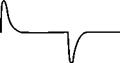
To obtain the dynamic balance of the bridge also, in this case a square wave is sent in the probe and the output signal of the bridge is observed on an oscilloscope. The purpose of the test is twofold: it can be used to optimize the bandwidth of the combined circuit sensor/amplifier, or simply to ensure that the behavior of the servo is stable. The time that the system takes to bring the bridge to balance is linked to the time constant, and therefore to the bandwidth of the system. On the arrival of the square
 |
|
Balancing a CTA with a square wave
wave, the system reacts in order to restore the resistance (and therefore the voltage) to the initial value (Figure 3.14).
The response time (Figure 3.15) is measured as the time, tw between the beginning of the pulse and a point on the descending curve whose ordinate is 3% of the total pulse. The bandwidth, or cut-off frequency, defined as the frequency at which the amplitude of the output signal is -3dB, can be expressed by
f(-3dB) = 1t1.3Tw
The frequency response can be optimized by adjusting the filter and the gain of the amplifier.
Instability of the system causes the appearance of oscillations in the response of the anemometer bridge that can take two aspects (Figure 3.16):
1. This type of oscillation, due to the difference in inductance between the active and passive arm of the bridge (e. g. the cable connecting the

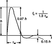 |
Determination of the time constant of a CTA
![]()
 |
Types of instability
probe to the anemometer is too long), can be removed by adjusting a winding in series with the passive resistance.
2. This oscillation is due both to low bandwidth, in which case it can be removed by increasing the gain, and to an excessive damping of the system, which may be reduced by acting on another winding.


