Our heavyweight helicopter equal in the world does not have
In Rostov started production of the most load-lifting rotary-wing car The Russian holding «Helicopt[...]

Everything about aircrafts and helicopters. News and events in aviation worldwide. Civil, transportation, military helicopters and airplanes.

Everything about aircrafts and helicopters. News and events in aviation worldwide. Civil, transportation, military helicopters and airplanes.

Everything about aircrafts and helicopters. News and events in aviation worldwide. Civil, transportation, military helicopters and airplanes.

Everything about aircrafts and helicopters. News and events in aviation worldwide. Civil, transportation, military helicopters and airplanes.


The helicopter is characterized by an abundance of interactional aerodynamic effects, often unseen in design but powerful in their, usually adverse, effects in flight. A principal source of interactions is the main rotor wake as it descends over the fuselage, empennage and through the tail rotor disc. The main rotor wake also interacts with the ground and with itself, in vortex-ring conditions. The modelling problem is therefore largely an extension of the problem of predicting the wake effects at the rotor disc; for interactional aerodynamics we are interested in the development of the wake within approximately one rotor diameter of the rotor. In this space-time frame, the wake is in unsteady transition between its early form as identifiable vorticity and fully developed rolled-up form, and presents a formidable modelling problem.
In recent times a number of factors have combined to increase the significance of interactional aerodynamics – higher disc loadings resulting in stronger downwash, more compact configurations often with relatively large fuselage and empennage areas and the increased use of helicopters in low level, nap-of-the-earth operations. From a design perspective, the most useful information relating to interactional aerodynamics is located in the reports of full and model scale testing. In Ref. 3.44, Prouty discusses a number of datasets showing the effects of rotor downwash on the empennage. A review of test results from a period of activity at Boeing helicopters is reported by Sheridan in Ref. 3.70. In this reference, interactions are classified into downstream (e. g., rotor/empennage upset loads, tail rotor/loss of effectiveness), localized (e. g., rotor/fuselage download, tail rotor/fin blockage), ground proximity (e. g., trim power, unsteady loads from ground vortex) and external interaction (e. g., helicopter/helicopter upset loads, ground winds) categories. One problem that has received considerable attention through testing is the interaction of the rotor downwash with the rear fuselage (tailboom) at low speed. In Ref. 3.71, Brocklehurst describes the successful implementation of fuselage strakes to control the separation of the circulatory flow caused by the downwash flowing over the tailboom in sideways flight. Reference 3.72 discusses a number of similar test programmes on US helicopters. In all these cases the use of the strakes reduced the tail rotor control and power requirements, hence recovering the flight envelope from the restrictions caused by the high tailboom sideforces.
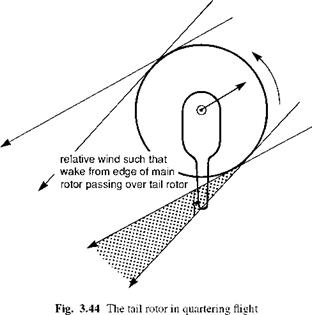
The interaction of the main rotor wake with the tail rotor has been the subject of an extensive test programme at the DRA Bedford (Refs 3.73, 3.74), aimed at providing data for interactional modelling developments. In Ref. 3.73, from an analysis of Lynx flight test data with an instrumented tail rotor, Ellin identified a number of regions of the flight envelope where the interactional aerodynamics could be categorized. Particular attention was paid to the so-called quartering-flight problem, where the tail rotor control requirements for trim can be considerably different from calculations based on an essentially isolated tail rotor. Figure 3.44 shows a plan view of the helicopter in quartering flight – hovering with a wind from about 45° to starboard. There exists a fairly narrow range of wind directions when the tail rotor is exposed to the powerful effect of the advancing blade tip vortices as they are swept downstream. A similar situation will arise in quartering flight from the left, although the tail rotor control margins are considerably greater for this lower (tail rotor) power condition. From a detailed study of tail rotor pressure data, Ellin was able to identify the passage of individual main rotor tip vortices through the tail rotor disc. Based on this evidence, Ellin constructed a Beddoes main rotor wake (Ref. 3.75) and was able to model, in a semi-empirical manner, the effect of the main rotor vortices on the tail rotor control
|
|
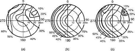
margin. Effectively the advancing blade tip vortices introduce a powerful in-plane velocity component at the tail rotor disc. For the case of the Lynx Mk 5, with its ‘top – forward’ tail rotor rotation direction, this leads to a reduction in dynamic pressure and an increase in control angle and power to achieve the same rotor thrust. Tail rotors with ‘top-aft’ rotations (e. g., Lynx Mk 7) do not suffer from this problem, and the control requirements, at least in right quartering flight, can actually be improved in some circumstances, although interactions with the aerodynamics of the vertical fin are also an important ingredient of this complex problem. Figure 3.45 shows the pedal control margin for Lynx Mk 5 hovering in a wind from all directions ‘around the clock’ out to 30 knots. Figure 3.45(a) presents Ellin’s flight measurements. The limiting condition corresponding to right quartering flight is shown as the 10% margin contour. The
|
Fig. 3.45 Comparison of the tail rotor pedal margin measured on the DRA research Lynx with theory: (a) flight; (b) Helisim; (c) Helisim corrected (Ref. 3.73) |
situation in left quartering flight manifests itself in a drawing out of the 60% contour as shown, although the situation is further complicated in left flight by the tail rotor experiencing vortex-ring flow states. Figure 3.45(b) shows the same result predicted by Helisim with an isolated tail rotor; clearly none of the non-uniformities caused by the interactions with the main rotor wake and fin is present. In comparison, Fig. 3.45(c) shows the Helisimpedal margin results after correction of the dynamic pressure experienced by the tail rotor, using the Beddoes main rotor wake. The non-uniformities in quartering flight are now well predicted, although in flight to the left, the predicted margin is still 10-15% greater than in flight. The results of Ellin’s research point towards the direction of improved modelling for main rotor wake/tail rotor interactions, although achieving real-time operation with the kind of prescribed wake used remains a significant task.
A similar investigation into the effects of main rotor wake/tail rotor interaction on yaw control effectiveness is reported in Ref. 3.76, using the University of Maryland Advanced Rotor Code (UMARC). For predicting the distribution of main rotor wake velocity perturbations behind the rotor, a free wake model was used and correlated against wind-tunnel test data. In general, a good comparison was found, except for the critical positions close to the main rotor tip vortices where peak velocities some 100% greater than predicted were measured. Correlation of predicted tail rotor control margin at the critical quartering flight azimuths was reasonable, although theory typically underestimated the control margins by about 10-15%. The UMARC analysis was conducted on an SH-2 helicopter with top-forward tail rotor rotation and the positive effects of main rotor wake/tail rotor interaction were predicted to be much stronger in theory than measured in flight. The Maryland research in this area represents one of the first applications of comprehensive rotor modelling to wake/tail interactions and their effects on flying qualities.
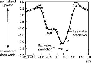
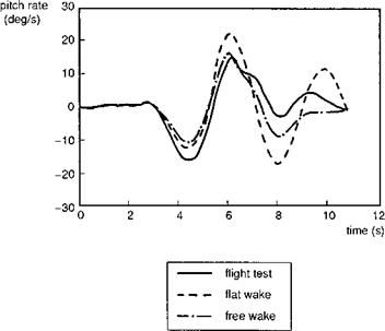
The series of papers by Curtiss and his co-workers at Princeton University report another important set of findings in the area of interactional aerodynamics; in this case, special attention was paid to the effect of the main rotor wake on the empennage (Refs 3.55, 3.77, 3.78). Reference 3.78 compares results using a ‘flat’ prescribed wake (Ref. 3.79) with a free wake (Ref. 3.80) for predicting the induced velocity distribution at the location of the horizontal stabilizer for a UH-60 helicopter. Comparison of the nondimensional downwash (normalized by momentum value of uniform downwash at the disc) predicted by the two methods, as a function of lateral displacement at the tail surface, is shown in Fig. 3.46. The UH-60 tailplane has a full span of about 0.5R. The simpler flat wake captures most of the features in the considerably more complex free wake model, although the peak velocities from the rolled-up wake on the advancing and retreating sides are overestimated by about 30% with the flat wake. The much stronger induced flow on the advancing side of the disc is clearly predicted by both models. The upwash outside the rotor disc (y /R > 1.0) is also predicted by both models. One of the applications studied in Ref. 3.78 involved the prediction of cross-coupling from sideslip into pitch, a characteristic known to feature quite large on the UH-60. From Figure 3.46, we can deduce that sideslip will give rise to significant variations in the levels of downwash at the horizontal stabilizer – a sideslip of 15°, for example, will cause a shift in the downwash pattern by about 0.25R, to left or right. Figure 3.47 compares the pitch rate response to a pedal doublet input at 100 knots; the flight test results are also plotted for comparison (Ref. 3.78). It can be seen that the powerful pitching moment, developing during the first second of the manoeuvre, is reasonably
|
Fig. 3.46 Comparison of flat and free wake predictions for normalized downwash at the horizontal stabilizer location; UH-60, p = 0.2 (Ref. 3.78) |
|
Fig. 3.47 Comparison of pitch rate response to pedal input; UH-60, 100 knots (Ref. 3.78) |
well predicted by both interactional aerodynamic models. As an aside, we would not expect to see any pitch response from the Helisim model until the yawing and rolling motions had developed. The free wake model appears to match flight test fairly well until the motion has decayed after about 10 s, while the flat wake underpredicts the oscillatory damping.
Ultimately, the value of interactional aerodynamic modelling will be measured by its effectiveness at predicting the degrading or enhancing effects on operational
performance. To reiterate, the motivation for developing an increased modelling capability for use in design and requirements capture, in terms of the potential pay-off, is very high. Much of the redesign effort on helicopters over the last 30 years has been driven by the unexpected negative impact of interactional problems (Ref. 3.81), and there is a real need for renewed efforts to improve the predictive capability of modelling. This must, of course, be matched by the gathering of appropriate validation test data.
At the time of writing, ‘operational’ simulation models with a comprehensive treatment of nonlinear, unsteady rotor and interactional aerodynamics are becoming commonplace in industry, government research laboratories and in academia. Some of these have been referred to above. The computational power to run blade-element rotor models, with elastic modes and quite sophisticated aerodynamic effects, in real time, is now available and affordable. The domain of flight dynamics is rapidly overlapping with the prediction of loads, vibration, rotor aeroelastic stability and aeroacoustics. Yet the overall effects on our understanding of helicopter flight dynamics, stemming from the vigorous developments in recent years, does not appear to have been cumulative. This is partly because of the human factor – the reservoirs of knowledge are people rather than reports and journal papers – but there is another important issue. In the author’s view, the pace associated with our ability to computer-model detailed fluid and structural dynamics has far outpaced our ability to understand the underlying causal physics. Even if the ‘perfect’ simulation model existed, its effective use in requirements capture, design and development would need to be underpinned by our ability to interpret the outputs meaningfully. While the perfect model does not yet exist, it is the vision of many rotorcraft engineers, but the achievement of this goal will need to be accompanied by two companion activities in the author’s view, or not realized at all. First, recalling how important the interplay between theory and experiment has been in the development of rotorcraft, confidence in simulation modelling will increase only through validation against test data. High-quality measurements of surface and flowfield aerodynamics and component loads are difficult and expensive to make and are often available only for commercially sensitive programmes. The focus needs to be on ‘generic’ test data, with an emphasis on manoeuvring flight and into areas at flight envelope boundaries where nonlinearities govern dynamic behaviour. Second, there needs to be renewed emphasis on the development of narrow range approximations that truly expose cause and effect and, just like the critical missing jigsaw piece, provide significant insight and understanding. However, the skills required to build a simulation model and those required to derive analytic approximations, while complementary, are quite different, and it is a mistake to assume that the former begets the latter. The importance of these integrated modelling skills needs to be recognized in university courses and industrial training programmes or there is a real danger that the analytical skills will be lost in favour of computational skills. Chapters 4 and 5 are concerned with working with simulation models, where validation and analytic approximation feature strongly.