Our heavyweight helicopter equal in the world does not have
In Rostov started production of the most load-lifting rotary-wing car The Russian holding «Helicopt[...]

Everything about aircrafts and helicopters. News and events in aviation worldwide. Civil, transportation, military helicopters and airplanes.

Everything about aircrafts and helicopters. News and events in aviation worldwide. Civil, transportation, military helicopters and airplanes.

Everything about aircrafts and helicopters. News and events in aviation worldwide. Civil, transportation, military helicopters and airplanes.

Everything about aircrafts and helicopters. News and events in aviation worldwide. Civil, transportation, military helicopters and airplanes.


Several of the important components of local blade incidence stem from the motion and shape of the blade relative to the hub. A characteristic of Level 1 (flight dynamics) modelling is the approximation of rigid blade motion for flap, lag and torsion. We have seen how the CSER can be used to represent the different types of flap retention system – teetering, articulated or bearingless. In MBC form, the dynamics of one – per-rev disc tilting are apparently well represented. Since the hub moments of interest are produced by the one-per-rev flapping, this level of approximation would appear to be adequate for problems in the frequency range of interest to the flight dynamicist. However, a significant simplification in the centre-spring approximation involves the relationship between the disc tilt and the hub moment. We have suggested earlier that the linear relationship is a powerful attribute of the centre-spring model; if we look more closely at the potential effects of elastic blade motion, we see that what appears to be a strength of the approximation in many cases is actually a weakness in others. With the centre-spring model, it can easily be shown that the moment computed from the disc tilt and the hub moment computed from the integrated aerodynamic loads are always in balance, and hence always in phase. More generally, for both articulated and hingeless rotor approximate models, this is not the case. Consider the blade flap moment (in rotating axes) at the hub, given by eqn 3.15, but expanded to show how the time-dependent generalized (modal) coordinates can be written as a summation of harmonics with coefficients am and bm, as in eqn 3.301:
CO R /со
M(r)(0, t) = Q2 (^n – 1) / mrSn(r)dr £ am cos mty + bm sin mty
n=1 л m=1
(3.301)
|
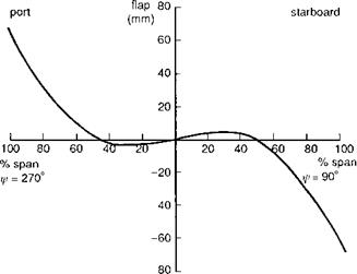
Fig. 3.43 Rotor blade shape at the advancing (90°) and retreating (270°) azimuth angles for Lynx at 150 knots |
Each mode will contribute to the rotating hub moment through the different harmonics, but only the first harmonic contribution to each will be transmitted through to result in quasi-steady fuselage motions. The extent of the contribution of higher modes to the hub moment depends entirely on the character of the aerodynamic forcing; the stronger the radial nonlinearity in the one-per-rev aerodynamic forces, the greater will be the excitation of the higher modes. Of course, the higher the frequency of the mode, the more attentuated will be its one-per-rev tip response, but equally, the hub moment for a given tip deflection will be greater for the higher modes. An illustration of the potential magnitude of contributions to the hub moment from higher elastic modes is provided by Fig. 3.43. The blade bending at azimuth stations 90° and 270° are shown for the Lynx rotor in trim at 150 knots, derived from the DRA aeroelastic rotor model. The rotor model used to compute the results shown includes first and second flap modes, first torsion and first lead-lag. The shape of the blade highlights the strong contribution from the second flap mode in the trim condition, with the ‘node’ (zero displacement) at about 50% radius. In fact, the hub moment, defined by the curvature of the blade at the hub, has an opposite sign to the tilt of the disc. The total hub rolling moment (in fuselage axes), computed from either the modal curvature or integrated aerodynamics, is about —1000 N m (to port), clearly in opposition to the disc tilt to starboard. For the case with only the fundamental flap mode retained, the hub moment derived from the first mode curvature is about +2000 N m (to starboard), while the aerodynamic moment integrates to about —600 N m (cf. Fig. 3.43). This result argues strongly for a harmony in the model between aerodynamic and dynamic formulations, particularly for high-speed flight (д > 0.3) when nonlinear aerodynamics and hence the effects of higher modes are likely to become more pronounced.
Shupe, in Ref. 3.36, presents results on the effect of the second flap mode over a wide range of conditions, supporting the above conclusion that the influence of the loading on the shape of the hingeless blade at high speed is significant, and higher order modes need to be included in simulation modelling for flight dynamics. Shupe also noted the powerful effects of blade twist on the distribution of out-of-plane bending between the first and second flap modes; twist tends to pull the blade loading inboard, hence leading to a radial aerodynamic distribution with a shape more like the second flap mode. A subtle effect that should be noted here is that the response of the second flap mode to one-per-rev aerodynamic loads will not feature the 90° phase shift associated with the first flap mode. The natural frequency of mode ‘flap 2’ is an order of magnitude higher than that for mode ‘flap 1’ and the phase lag at one-per-rev will be very small. Hence, lateral cyclic (9c) will lead primarily to longitudinal disc tilt (fic) in mode ‘flap 2’, thus having a stronger effect on crosscoupling than the direct response. The influence of the second flap mode in flight dynamics is yet to be fully explored and remains a research topic worthy of further investigation.
Blade dynamic twist will clearly have a major effect on local blade incidence, flapping and hub moments and can arise from a number of sources. Any offset of the blade chordwise centre of mass or elastic axis from the quarter chord will result in a coupling of the flap and torsion DoFs in the elastic modes. The shift of the chordwise aerodynamic centre due to compressibility, stall or by design through swept tip planforms will also be a source of torsional moments from the section aerodynamic pitching moment. References 3.66-3.68 report results of flight dynamics simulation models that incorporate elastic modes, paying particular attention to the effect of elastic torsion. For the cases studied in both Ref. 3.67, using the FLIGHTLAB simulation model, and Ref. 3.68, using the UM-GENHEL simulation model, elastic torsion was shown to have a negligible effect on aircraft trim, stability and dynamic response; comparisons were made with test data for the articulated rotor UH-60 helicopter in hover and forward flight. Articulated rotor helicopters are normally designed so that the blade pitch control is positioned outboard of the flap and lag hinges, thereby reducing kinematic couplings. On hingeless rotors, combined flap and lag bending outboard of the pitch control will produce torsional moments leading to elastic twist of the whole blade or flexing of the control system. This feature was described in the context of the design of the Westland Lynx helicopter in Ref. 3.69. The combination of an inboard flapping element with high lag stiffness and a circular section element with matched flap and lag stiffnesses outboard of the feathering hinge resulted in a minimization of torsion-flap-lag coupling on Lynx. For both articulated and hingeless rotors, it should be clear that the potential for elastic couplings and/or forced torsional response is quite high, and even with designs that have emphasized the reduction of the sources of coupled torsional moments, we can expect the combination of many small elastic and particularly unsteady aerodynamic effects to lead to both transient and steady-state elastic twist.
Aeroelastic effects clearly complicate rotor dynamics but are likely to be an important ingredient and a common feature of future high-fidelity rotorcraft simulations. It will be clear to the serious student of the subject that most of the approximations lie in the formulation of the aerodynamic theory, particularly the dynamic inflow, but the degree of ‘aeroelastic’ modelling required to complete the feedback loop correctly is not well researched. As new rotor designs with tailored elastic properties and ‘flexible’ surfaces become mature enough for application, we should expect an associated increase in the motivation for understanding and developing more general and definitive rules for the effects of aeroelastics on flight stability and control.