Our heavyweight helicopter equal in the world does not have
In Rostov started production of the most load-lifting rotary-wing car The Russian holding «Helicopt[...]

Everything about aircrafts and helicopters. News and events in aviation worldwide. Civil, transportation, military helicopters and airplanes.

Everything about aircrafts and helicopters. News and events in aviation worldwide. Civil, transportation, military helicopters and airplanes.

Everything about aircrafts and helicopters. News and events in aviation worldwide. Civil, transportation, military helicopters and airplanes.

Everything about aircrafts and helicopters. News and events in aviation worldwide. Civil, transportation, military helicopters and airplanes.


The moments due to the aerodynamic forces acting on the wing are usually determined about one of the two reference axes, namely the axes passing through the leading edge and the aerodynamic center. The moments obtained are nondimensionalized following a similar procedure that was used to nondimensionalize the lift. Let us calculate the pitching moment about the leading edge due to the pressure acting on the surface of the wing, shown in Figure 4.28. Let us assume that the contribution of chordwise component of the pressure force to the moment is negligibly small. Thus, the pitching moment about the
leading edge due to the pressure force acting on the surface element of area (dxdy) located at a distance x from the leading edge is:
dM0 = p x (dxdy) x x. (4.27)
 |
The net pitching moment due to the pressure force acting on the wing can be obtained by integrating Equation (4.27) over the entire wing surface. The net pitching moment is given by:
In Equation (4.32) the wing chord c is used as a parameter because this derivation is for a rectangular wing in Figure 4.28. That is the mean aerodynamic chord is used together with wing area S to nondimensionalize the pitching moment.
The pitching moment coefficient for a wing section of unit span, referred to as section pitching moment coefficient, becomes:
where m0 is the section pitching moment. The section pitching moment coefficient depends on the camber and thickness ratio of the wing. Similar to section lift coefficient cb section pitching moment coefficient
0.4 – 0.2 –
°.° – —————
– 0.2 –
– 0.4 Li___ I__ I__ I__ I___
– 20 – 10 0 10 20
a, degrees
Figure 4.30 Variation of section pitching moment coefficient with angle of attack.
cm about the aerodynamic center is independent of angle of attack. Typical variation of section pitching moment coefficient about the aerodynamic center with angle of attack is as shown in Figure 4.30.
Thus, the aerodynamic center is that point along the chord where all changes in lift effectively take place. Since the moment about the aerodynamic center is the product of a force (the lift that acts at the center of pressure) and an arm length (the distance from the aerodynamic center to the center of pressure), the center of pressure must move toward the aerodynamic center as the lift increases.
4.11 Summary
Transformation of a flow pattern essentially amounts to the transformation of a set of streamlines and potential lines, whilst the transformation of individual lines implies the transformation of a number of points.
To transform the points specified by the Cartesian coordinates x and y, in the physical plane, given by z = x + iy, to a transformed plane given by Z = § + in we need to expand the transformation function Z = f (z) = § + in, equate the real and imaginary parts and find the functional form of § and n, in terms of x and y.
For a given flow pattern in the physical plane, each streamline of the flow can be represented by a separate stream function. Transferring these stream functions, using the transformation function, Z = f (z), the corresponding streamlines in the transformed plane can be obtained.
The main use of conformal transformation in aerodynamics is to transform a complicated flow field into a simpler one, which is amenable to simpler mathematical treatment.
The main problem associated with this transformation is finding the best transformation function (formula) to perform the required operation. Even though a large number of mathematical functions can be envisaged for a specific transformation.
A transformation, which generates a family of aerofoil shaped curves, along with their associated flow patterns, by applying a certain transformation to consolidate the theory presented in the previous sections, is the Kutta-Joukowski transformation.
Kutta-Joukowski transformation is the simplest of all transformations developed for generating aerofoil shaped contours. Kutta used this transformation to study circular-arc wing sections, while Joukowski showed how this transformation could be extended to produce wing sections with thickness t as well as camber.
In our discussion on Kutta-Joukowski transformation, it is important to note the following:
• The circle considered, in the physical plane, is a specific streamline. Essentially the circle is the
stagnation streamline of the flow in the original plane 1 (z – plane).
• The transformation can be applied to the circle and all other streamlines, around the circle, to generate the aerofoil and the corresponding streamlines in plane 2 (f-plane) or the transformed plane. That is, the transformation can result in the desired aerofoil shape and the streamlines of the flow around the aerofoil.
It is convenient to use polar coordinates in the z-plane and Cartesian coordinates in f-plane. The Kutta-Joukowski transformation function is:
b2
Z = Z + in = z +—- ,
z
where b is a constant.
Now, expressing z as z = re’e, where r and в are the polar coordinates, and on expanding, we get:
. ie b2
Z + in =re + —в
b2
= r (cos в + i sin в) +——- (cos в — i sin в).
r
Equating the real and imaginary parts, we get:
 |
These expressions for Z and n are the general expressions for the transformation of the basic shape, namely the circle in the z-plane, to any desired shape in the f-plane.
For transforming a circle of radius a to a straight line, the constant b in the Joukowski transformation function should be set equal to a, and the center of the circle should be at the origin.
For transforming a circle to an ellipse using the Kutta—Joukowski transformation function:
b2
Z = z + —
z
the circle should have its center at the origin in the z-plane, but the radius of the circle should be greater than the constant b, in the above transformation function, that is, a > b.
To transform a circle into a symmetrical aerofoil, the center of the circle in the z-plane should be shifted from the origin and located slightly downstream of the origin, on the x-axis. This shift would cause asymmetry to the profile (about the ordinates of the transformed plane) of the transformed shape obtained with the Kutta—Joukowski transformation function.
![]()
Z=
are the coordinates of a symmetrical aerofoil profile. The chord of the aerofoil is 4b. The maximum thickness of the aerofoil occurs where йп/йв = 0.
The maximum thickness is at the chord location, given by:
n
9 = 2b cos — = b.
9 3
This point (b, 0), from the leading edge of the aerofoil, is the quarter chord point. The thickness to chord ratio of the aerofoil is:
![]() t
t
c
At the trailing edge of the aerofoil, the slope of its upper and lower surfaces merge. This kind of trailing edge would ensure that the flow will leave the trailing edge without separation. But this is possible only when the trailing edge is cusped with zero thickness. Thus, this is only a mathematical model. For actual aerofoils, the trailing edge will have a finite thickness, and hence, there is bound to be some separation, even for the thinnest possible trailing edge.
For transforming a circle to a cambered aerofoil, using Joukowski transformation, the center of the circle in the physical plane has to be shifted to a point in one of the quadrants.
are the coordinates representing a cambered aerofoil.
The thickness-to-chord ratio for a cambered aerofoil is:
The thickness-to-chord ratio is maximum at ви = 60°. Thus:
This maximum is also at the quarter chord point, as in the case of symmetrical aerofoil.
The camber of an aerofoil is the maximum displacement of the mean camber line from the chord. The mean camber line is the locus of mid-points of lines drawn perpendicular to the chord. In other words, the camber line is the bisector of the aerofoil profile thickness distribution from the leading edge to the trailing edge.
Percentage camber = — x 100%.
Transformation of a circle with its center shifted above (or below) the origin, on the ordinate in the z-plane, with the transformation function Z = z + b2/z results in a circular arc.
9 = 2b cos в
where § and n, respectively, are the expressions for the abscissa and ordinates of the circular arc, in the transformed plane.
For the transformed circular arc, the chord is 4b.
![]() Camber/chord
Camber/chord
1
= – tan в. 2 в
But for small в, tan в ^ в. Therefore, the percentage camber for the circular arc becomes 100 в/2.
The postulation that “the aerofoil generates sufficient circulation to depress the rear stagnation point from its position, in the absence of circulation, down to the sharp trailing edge” is known as Joukowski hypothesis. This condition of realizing full Joukowski circulation, resulting in flow without wake is known as Kutta condition.
The Kutta condition can be stated as follows:
"A body with a sharp trailing edge which is moving through a fluid will create about itself a
circulation of sufficient strength to hold the rear stagnation point at the trailing edge."
The Kutta condition is significant when using the Kutta—Joukowski theorem to calculate the lift generated by an aerofoil. The value of circulation of the flow around the aerofoil must be that value which would cause the Kutta condition to exist.
The Kutta condition allows an aerodynamicist to incorporate a significant effect of viscosity while neglecting viscous effects in the conservation of momentum equation. It is important in the practical calculation of lift on a wing.
The Kutta condition does not apply to unsteady flow. Mathematically, the Kutta condition enforces a specific choice among the infinite allowed values of circulation.
Joukowski hypothesis directly relates the lift generated by a two-dimensional aerofoil to its incidence, as well as indicates the significance of the thickness to chord ratio and camber of the aerofoil in the lift generation.
As the flow process develops, which takes place very quickly, the circulation around the aerofoil section is generated and the aerofoil experiences lift.
1 2
L = – pVl SCl,
where Cl is the lift coefficient and S is the projected area of the wing planform, normal to the direction of freestream flow. The area S is given by:
S = span x chord.
The chord of the profile is 4b. Therefore, the area of the profile, per unit span, becomes S = 4b. Thus, the lift is:
1 2
L = – pV24bCL
= 2pV 2bCL.
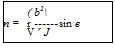
Equating the above two expressions for lift, we get the lift coefficient as:
a
CL = 2n— sin (a + 0). b
But,
a/b = (1 + e).
Therefore,
This is the lift coefficient of a two-dimensional aerofoil, in terms of thickness to chord ratio (t/c = 1.299e), percentage camber (100 в/2), and angle of incidence a.
The ideal lift curve slope, ax, I, for small values of eccentricity e, angle of incidence a and camber в, is:
![]() ажі —
ажі —
This is the theoretical value of lift curve slope per radian of angle of attack, a. It is seen that, the lift curve slope is independent of the angle of attack.
The coordinates of the transformed aerofoil profile are:
x = a cos 9′ + be y = a sin 9 + Ьв(1 + e).
With a = (b + be), the above coordinate expressions become:
x = (b + be) cos 9 + be
y = (b + be) sin 9′ + be(1 + e).
For finding the velocity distribution around a given aerofoil, it is necessary to relate the angle of incidence a to the circulation Г around the aerofoil. This is done by applying the Joukowski hypothesis. In reality, the full Joukowski circulation required to bring the rear stagnation point to the trailing edge is not realized, because of the following:
• Air is a viscous fluid, and the flow near the trailing edge of an aerofoil is modified by the presence of the boundary layer and wake, caused by the viscosity.
• The zero thickness for the trailing edge, stipulated by the Joukowski hypothesis, is not possible in practice. Therefore, the trailing edge must be rounded to some degree of curvature. The finite thickness of the trailing edge owing to this rounding-off forces the rear stagnation point to deviate from the position given in the ideal case.
Therefore, if Г is the full Joukowski circulation (theoretical circulation), it can be assumed that, the practical value of circulation is only £Г, where k is less than unity.
The velocity on the aerofoil is:
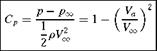
For incompressible flow, the pressure coefficient is given by:
|
|
Knowing the distribution of Va/Vx, over the aerofoil, the pressure coefficient around the aerofoil can be estimated.
An aerofoil is a streamlined body that would experience the largest value of lift-to-drag ratio, in a given flow, compared to any other body in the same flow. In other words, in a given flow the aerodynamic efficiency (L/D) of an aerofoil will be the maximum.
The pressure and shear forces can be integrated over the surface of the aerofoil to obtain the resultant aerodynamic force, Fad, which acts at the center of pressure (kcp) of the aerofoil.
The forces acting on an aircraft in level flight are the lift L, drag D, thrust T and weight W.
For a steady, unaccelerated level flight in a horizontal plane:
• The sum of the forces along the flight path is zero.
• The sum of the forces perpendicular the flight path is zero.
When the angle of incidence a is small, the component of thrust parallel to the freestream flow direction is only slightly less than the thrust itself. Therefore, for equilibrium:
L = W T = D.
The lift acting ahead of center of gravity will produce a nose-up (positive) moment about the center of gravity. The aircraft is said to be trimmed, when the sum of the moments about the cg is zero, that is:
Thus, a force from a control surface located aft of the cg, for example, the horizontal tail surface Lt is required to produce a nose-down (negative) pitching moment about the cg, which could balance the positive moment produced by Lwb. The tail surface producing Lt also produces a drag force which is known as the trim drag. The trim drag may vary from 0.5% to 5% of the total drag of the aircraft.
In addition to the lift and drag acting in the pitch or xz-plane, there is a side force acting on the aircraft. The side force is the component of force in the direction perpendicular to both the lift and the drag. The side force acting towards the starboard (right) wing is referred to as positive.
Usually the aerodynamic force will not act through the cg (which is also taken as the origin of the airplane’s axis system). The moment due to the resultant force acts at a distance from the origin may be divided into three components, referred to the airplane’s axes. The three moment components are the pitching moment M, the rolling moment L and the yawing moment N:
• Pitching moment is the moment acting about the lateral axis (y-axis). It is the moment due to the lift and drag acting on the aircraft. Pitching moment causing nose-up is regarded positive.
• Rolling moment is the moment acting about the longitudinal axis (x-axis) of the aircraft. Rolling moment is generated by a differential lift generated by the ailerons, located closer to the wingtips. Rolling moment causing the right (starboard) wingtip to move downward is regarded positive.
• Yawing moment is the moment acting about the vertical (z-axis) of the aircraft. Yawing moment tends to rotate the aircraft nose to the right is regarded positive.
The primary parameters governing the magnitude of the aerodynamic forces and moments are the following:
• Geometry of the aerofoil.
• Angle of attack, namely the aircraft attitude in the pitch (xz) plane relative to the flight direction.
• Vehicle size.
• Freestream velocity.
• Freestream flow density.
• Reynolds number (viscous effects).
• Mach number (compressibility effects).
The geometrical section of a wing obtained by cutting it by a vertical plane parallel to the centerline of the aircraft is called aerofoil section. The lift generated and the stall characteristics of a wing strongly depends on the geometry of the aerofoil sections that make up the wing. The geometric parameters that dictate the aerodynamic characteristics of the aerofoil section are; the leading-edge radius, the mean camber line, the maximum thickness and the thickness distribution of the profile, and the trailing-edge angle.
The geometry of many aerofoil sections is uniquely defined by the NACA designation for the aerofoil. Aerofoil geometry are usually characterized by the coordinates of the upper and lower surface. It is often summarized by a few parameters such as: maximum thickness, maximum camber, position of max thickness, position of max camber, and nose radius.
The shape of the NACA aerofoils is described using a series of digits following the word “NACA.”
In NACA 4-Digit series the first digit implies the maximum camber in percentage of chord (c), the second digit gives the position of maximum camber in 1/10 of chord, the last two digits give the maximum thickness in percentage of chord. For example,
In NACA 5-digit series the first digit gives approximate maximum camber in percentage of chord, the second and third digits give the position of maximum camber in 2/100 of chord and the last two digits give the maximum thickness in percentage of chord. This NACA 23012 is an aerofoil with maximum camber as 2% of c, position of maximum camber at 60% of chord and t/c = 0.12.
Four- and five-digit series aerofoils can be modified with a two-digit code preceded by a hyphen in the following sequence:
1. One digit describing the roundness of the leading edge with 0 being sharp, 6 being the same as the original aerofoil, and larger values indicating a more rounded leading edge.
2. One digit describing the distance of maximum thickness from the leading edge in tens of percentage of the chord.
1-series:
A new approach to aerofoil design pioneered in the 1930s in which the aerofoil shape was mathematically derived from the desired lift characteristics. Prior to this, aerofoil shapes were first created and then had their characteristics measured in a wind tunnel. The 1-series aerofoils are described by five digits in the following sequence:
1. The number “1” indicating the series.
2. One digit describing the distance of the minimum pressure area in tens of percent of chord.
3. A hyphen.
4. One digit describing the lift coefficient in tenths.
5. Two digits describing the maximum thickness in percentage of chord.
In NACA 6-digit series the first digit refers to the series, the second digit gives the location of minimum Cp in 1/10 chord, the third digit gives the half width of low drag bucket in 1/10 of CL, the fourth digit gives the ideal CL in tenths of CL, the fifth and sixth digits give the max thickness in percentage of chord. In NACA 7-Digit Series:
1. The number “7” indicating the series.
2. One digit describing the distance of the minimum pressure area on the upper surface in tens of percentage of chord.
3. One digit describing the distance of the minimum pressure area on the lower surface in tens of percentage of chord.
4. One letter referring to a standard profile from the earlier NACA series.
5. One digit describing the lift coefficient in tenths.
6. Two digits describing the maximum thickness in tens of percentage of chord.
7. “a =” followed by a decimal number describing the fraction of chord over which laminar flow is maintained. a = 1 is the default if no value is given.
In NACA 8-Digit series profiles are supercritical aerofoils designed to independently maximize airflow above and below the wing. The numbering is identical to the 7-series aerofoils except that the sequence begins with an “8” to identify the series.
NASA Aerofoils
A concerted effort within the National Aeronautics and Space Administration (NASA) during the 1960s and 1970s was directed toward developing practical aerofoils with two-dimensional transonic turbulent flow and improved drag divergence Mach numbers while retaining acceptable low-speed maximum lift and stall characteristics and focused on a concept referred to as the supercritical aerofoil. This distinctive aerofoil shape, based on the concept of local supersonic flow with isentropic recompression, was characterized by a large leading-edge radius, reduced curvature over the middle region of the upper surface, and substantial aft camber.
The early phase of this effort was successful in significantly extending drag-rise Mach numbers beyond those of conventional aerofoils such as the National Advisory Committee for Aeronautics (NACA) 6-series aerofoils. These early supercritical aerofoils (denoted by the SC (phase 1) prefix), however, experienced a gradual increase in drag at Mach numbers just preceding drag divergence (referred to as drag creep). This gradual buildup of drag was largely associated with an intermediate off-design second velocity peak (an acceleration of the flow over the rear upper-surface portion of the aerofoil just before the final recompression at the trailing edge) and relatively weak shock waves above the upper surface. The chord line is defined as the shortest (straight) line connecting the leading and trailing edges.
The geometrical angle of attack a is the angle between the chord line and the direction of the undisturbed freestream.
Mean camber line is the locus of the points midway between the upper and lower surfaces of the aerofoil. One of the primary effects of camber is to change the zero-lift angle of attack, a0l. For symmetrical
aerofoils, zero lift is at a = 0 and for cambered aerofoils, zero lift is at negative a for positive camber and vice versa.
The thickness distribution and the maximum thickness strongly influence the aerodynamics characteristics of the aerofoil section. The thickness distribution for an aerofoil affects the pressure distribution and the character of the boundary layer.
The trailing-edge angle influences the location of the aerodynamic center, the point about which the section moment coefficient is independent of angle of angle of attack, a. The aerodynamic center of this aerofoil sections in a subsonic flow is theoretically located at the quarter-chord point.
Aircraft wings are made up of aerofoil sections discussed in the preceding section. Aerofoil sections are placed along the span of a wing.
The relevant parameters used to define the aerodynamic characteristics of a wing are rectangular, unswept trapezoidal, swept and delta configurations.
Wing area is the plan surface area of the wing.
Wingspan is the distance between the tips of port and starboard wings.
Average chord is the geometric average of the chord distribution over the length of the wing span.
Aspect ratio is the ratio of the span and the average chord.
Root chord is the chord at the wing centerline. Tip chord the chord at the wing tip.
Taper ratio is the ratio of the tip chord to root chord.
Sweep angle is usually measured as the angle between the line of 25% chord and a perpendicular to the root chord.
Mean aerodynamic chord is an average chord which, when multiplied by the product of the average section moment coefficient, the dynamic pressure, and the wing area, gives the moment for the entire wing.
Dihedral angle is the angle between a horizontal plane containing the root chord and a plane midway between the upper and lower surfaces of the wing. If the wing lies below the horizontal plane, it is termed an anhedral angle.
Geometric twist defines the situation where the chord lines for the spanwise distribution of all the aerofoil sections do not lie in the same plane.
If the incidence of the aerofoil sections relative to the vehicle axis decrease toward the tip, the wing has a “wash-out.” If the angle of incidence increases toward wing tip, the wing has “wash-in.”
For thin aerofoils at low angle of attack, the lift results mainly from the pressure distribution (that is, pressure forces). The shear forces due to viscosity acts primarily in the chordwise direction and contributes mainly to the drag.
When the boundary layer is thin, the pressure distribution around the aerofoil can be regarded equivalent to that due to an inviscid flow. Thus, the pressure distribution is independent of Reynolds number and does not depend on whether the boundary layer is laminar or turbulent.
The lift coefficient, is defined:
Cl =
where L is the lift and S is the wing planform area.
Theoretical value of two-dimensional lift curve slope is 2n, that is:
dCi
Cl, a = – у- = 2Я.
da
The moments due to the aerodynamic forces acting on the wing are usually determined about one of the two reference axes, namely the axes passing through the leading edge and the aerodynamic center. The moments obtained are nondimensionalized following a similar procedure that was used to nondimensionalize the lift.
The net pitching moment is given by:
Mo =11 (p — pO) x dxdy.
The pitching moment coefficient is:
Exercise Problems
1. If the pressure coefficient at a point on an aerofoil in a freestream flow of speed 70 m/s is —3.7, determine the flow velocity at that point.
[Answer: 151.76 m/s]
2. A two-dimensional wing of span 20 m and chord 1.1 m, thickness-to-chord ratio 12% and percentage camber 10% at an angle of attack of 3° in a uniform air stream at 1 atm and 22 °C and 220 km/h experiences a lift of 15 000 N. Determine the circulation around the wing and the lift coefficient, assuming the flow as incompressible and inviscid.
[Answer: Г = 10.26 m2/s, CL = 0.373]
3. A tapered wing of span 15 m and root chord 4 m has a planform area of 37.5 m2. Find (a) the tip chord and (b) the mean aerodynamic chord of the wing.
[Answer: (a) 1 m, (b) 2.8 m]
4. A wing of taper ratio 3 has a planform area of 45 m2. If the span is 16 m, determine the root and tip chords of the wing.
[Answer: 4.218 m, 1.406 m]
5. If the section lift acting on a two-dimensional wing of chord 2 m, flying at 250 km/h in sea level altitude is 3000 N/m, when the angle of attack is 4° and section lift curve slope is 0.11, determine the zero lift angle of attack of the wing.
[Answer: —0.618°]
6. The section lift coefficient of a two-dimensional wing flying at 3.2° angle of attack is 0.6. If the zero lift angle of attack is —1.8°, determine the lift curve slope of the wing.
[Answer: 0.12]
7. A tapered wing of tip chord 3 m has wing area 220 m2 and aspect ratio 4. Find (a) the root chord and (b) the wing span. (c) Also, find the expression for the chord in terms of transverse coordinate.
[Answer: (a) 11.83 m, (b) 29.66 m, (c) 11.83 — 0.595 y]
8. A NACA 612-415 aerofoil flies at 400 km/h at an altitude where the air density is 0.082 kg/m3. Determine the wing loading of the aerofoil.
[Answer: 202.5 N/m2]
9. Identify the number of the NACA profile with 3% maximum camber located at 30% from the leading edge, with a thickness of 10% of the chord.
[Answer: NACA 3310]
10. Identify the number of the NACA profile with 0 camber and thickness to chord ratio of 12%.
[Answer: NACA 0012]
11.
If the fineness ratio of the ellipse obtained by transforming a circle of unit radius, with Kutta—Joukowski transformation, is 4, determine the eccentricity.
12. A symmetrical aerofoil is obtained by transforming a circle of unit radius, with Kutta-Joukowski transformation function. If the eccentricity is 0.1, find the maximum value of thickness to chord ratio.
[Answer: 0.13]
13. A cambered aerofoil is obtained by transforming a circle of unit radius, with Joukowski transformation function. If the percentage camber is 3.2, determine the location of the circle center in the physical plane.
[Answer: (0.024, 0.064)]
14. If the maximum thickness of a 14% cambered Joukowski aerofoil is at n/2.5, determine the eccentricity.
[Answer: 0.112]
15. If a two-dimensional Joukowski aerofoil of thickness to chord ratio 12% and camber 3% in an ideal flow experiences a lift coefficient of 0.8, determine (a) the angle of incidence and (b) the lift curve slope.