Our heavyweight helicopter equal in the world does not have
In Rostov started production of the most load-lifting rotary-wing car The Russian holding «Helicopt[...]

Everything about aircrafts and helicopters. News and events in aviation worldwide. Civil, transportation, military helicopters and airplanes.

Everything about aircrafts and helicopters. News and events in aviation worldwide. Civil, transportation, military helicopters and airplanes.

Everything about aircrafts and helicopters. News and events in aviation worldwide. Civil, transportation, military helicopters and airplanes.

Everything about aircrafts and helicopters. News and events in aviation worldwide. Civil, transportation, military helicopters and airplanes.


Satisfaction of the longitudinal trim at this stage in Fig. 4.5 does not guarantee a valid trim; estimates of the lateral trim have been used and the process now has to continue with the aim of correcting both of these. Having derived a new estimate for the lateral trim, the longitudinal cycle will then need to be repeated until all six force and moment equations balance properly. But the next stage in Fig. 4.5 involves the calculation of a new value for the main rotor downwash (D in Fig. 4.5), which is itself an iterative process (see Chapter 3), and the estimation of the main rotor torque and power required (E). With these calculations performed, the tail rotor thrust can be estimated from the yawing moment equation (F), the lateral flapping corrected from the rolling moment
|
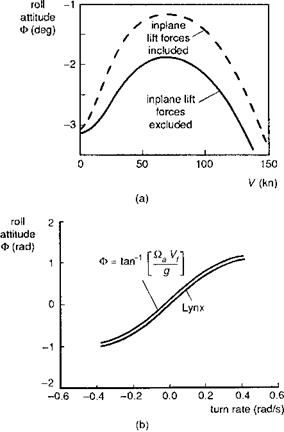
equation (G) and the new value of roll attitude derived from the sideforce equation (H). A check is now made on the convergence of the roll attitude in the same way as described for the pitch attitude, with defined convergence tolerance and damping factor. For both pitch and roll attitude, the number of iterations required, and hence the speed of convergence, depends critically on the initial guesses; clearly, the further away from the correct solution that the initial guess is, the longer will convergence take. For straight flight, setting the initial values to zero is usually adequate for fairly rapid convergence. Figure 4.8(a) shows the variation in roll attitude with forward speed for the Lynx, illustrating the powerful effect of adding the in-plane lift loads in the calculation of rotor sideforce (see Chapter 3). In turning flight, the bank angle will become large, and an initial guess based on the rules of simple circular motion is usually sufficient to ensure rapid convergence, i. e.,
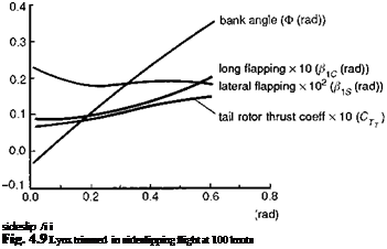 |
Figure 4.8(b) shows how the Lynx roll attitude varies with turn rate at the 80-knot trim point. The approximate result given by eqn 4.34 is plotted for comparison and shows how accurate by this simple kinematic relationship predicts the Lynx result.
At large turn rates, in forward flight, the roll attitude iteration can become sensitive to the sign of the error between the initial guess and the correct solution. If the initial Ф results in a lateral acceleration greater than the weight component, then this simple trim procedure will diverge, no matter how much damping is added. The trim iteration will converge only when a Ф estimate greater than the solution is introduced. These details will need to be considered when a simple trim algorithm is used, but they are usually catered for in the more sophisticated nonlinear numerical search algorithms. In sideslip flight, the bank angle also varies significantly as shown in Fig. 4.9, where Lynx trim results for bank angle, flapping angles and tail rotor thrust coefficient are plotted. The bank angle is approximately linear with sideslip up to about 30°, with both aerodynamic and gravitational sideforces on the aircraft varying approximately as sin в. Longitudinal flapping increases at a greater rate than lateral flapping, as the rotor thrust is tilted further forward to compensate for the increased drag in sideslip flight.