Our heavyweight helicopter equal in the world does not have
In Rostov started production of the most load-lifting rotary-wing car The Russian holding «Helicopt[...]

Everything about aircrafts and helicopters. News and events in aviation worldwide. Civil, transportation, military helicopters and airplanes.

Everything about aircrafts and helicopters. News and events in aviation worldwide. Civil, transportation, military helicopters and airplanes.

Everything about aircrafts and helicopters. News and events in aviation worldwide. Civil, transportation, military helicopters and airplanes.

Everything about aircrafts and helicopters. News and events in aviation worldwide. Civil, transportation, military helicopters and airplanes.


Detailed wind tunnel results for the Gottingen 801 profile are given in Appendix 2. For any aerofoil of this type, there is a critical wing Reynolds number at which separation is followed by re-attachment Above this Re, the wing will work well, below it, it will be very
inefficient A model with such a profile below critical Re will hardly be capable of flight.
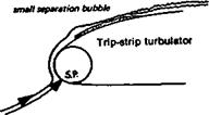
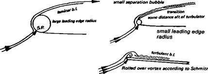
The first important investigation of wing profiles at model aircraft values of the wing Re were made at Cologne during the late nineteen thirties by F. W. Schmitz. His book, Aerodynamik des Flugmodells (Aerodynamics of Flying Models) published in 1942 remains a classic.* Because of the war Schmitz’s work did not become generally known ■until after 1946, but since then his recommendations have been widely accepted and further work by K. Kraemer and G. Muessman and many others more recently, has tended to confirm and amplify most of Schmitz’s original findings. This has led to the concentration of effort by modellers on aerofoil profiles with low critical Reynolds numbers. Techniques and devices have been adopted which ensure that the boundary layer over small model wings is made turbulent as early as possible. This causes an increase in skin drag, but this loss is far less significant than the prevention of early flow separation on the grand scale indicated by Figure 8.3.
8.2 HYSTERESIS
One of Schmitz’s original diagrams is reproduced in Figure 8.4. An accurately made model of the N-60 was suspended in a wind tunnel and the speed of the tunnel fan was gradually increased to give a rising Reynolds number. Coefficients of lift, drag and pitching moment were measured stage by stage. Consider first the lift curve (Cl). The flow is sub-critical, completely separated, at the lower Re values, and although the lift improves slightly as the Re rises, the super-critical condition does not arrive until Re 147,000 when die curve leaps to a higher value. In the drag diagram (C<j), there is a corresponding sudden fall. This marked change of efficiency is indicative of re-attachment of the flow, and is accompanied by a change of the pitching moment In the next test, the flow speed was gradually reduced, and, as before, the coefficients were measured at each stage. This time, super-critical flow continued down to Re 82,400, as shown by Schmitz’s curve C’ to E’. Then, with little warning, the flow separated and the lift collapsed, with large rise in drag. Between Re 82,400 and 147,000 there is what is known as hysteresis loop. Schmitz found that, starting with separated, sub-critical flow between Re 82,400 and 147,000 he could cause a great improvement in aerofoil performance if he could make the flow turbulent This he did by briefly inserting a stick into the tunnel airflow stream ahead of the wing model. The flow immediately re-attached, and the lift leapt up to the higher curve. On removing this crude ‘turbulator’, the flow remained attached. Below 82,400, i. e. outside the loop, on the low Re side, the turbulator had a similar effect when inserted, but as soon as it was removed, the flow returned to sub-critical and separated from the wing. At other angles of attack, the critical Re was different. Schmitz found that flow separation on the N-60, without turbulator, was inevitable below Re 63,000 at any angle of attack. This figure is usually quoted as the ‘critical Re’ for this aerofoil, but at various angles of attack the separation occurs at different Re. Even at Re 168,000, a hysteresis loop was still present at high angles of attack, hence the N-60, for reliable use on models flying at high Cl, would be best fitted with some device to introduce artificial turbulence into the airflow.
Schmitz also tested the much thicker, highly cambered profile, Gottingen 62S, which was found to have a higher critical Re than the N-60, the loop beginning at 105,000. But
♦Apart from copies at the library of R. A.E., Famborough, and at die Science Museum Library in Smith Kensington, an English translation is available from the British Library, catalogued as R. T. P. Translations Numbers 2460, 2204, 2457 and 2442. A N. A.C. A. translation is also obtainable through the U. S. Information Service. A new German edition was published in 1976.
 |
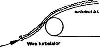
again, the introduction of a turbulator, in the form of a wire mounted just ahead of the leading edge (see Fig. 8.5), brought the critical value down to about 50,000. Neither the N-16 nor the Go 625 is popular among modellers, but they are representative of a type of profile which remains in widespread use. In 1958-59, G. Muessmann, investigating profiles for gas and steam turbine blades, published test results on four flat-bottomed aerofoils of varying thicknesses and cambers. These closely resemble the profiles favoured for beginners’ and sport models, and tailplanes, the so-called ‘Clark Y’ type aerofoils. From these tests it was found that the Go 796, generally similar to the Clark Y, had a critical Re (lowest value) very similar to that of the N-60. The well-known NACA 4412 is about the same. On the other hand, Muessman’s 20% thick profile, the Go 798, had a critical Re similar to the equally thick Gd 625, while the thin Muessman Go 795 began to show signs of general flow separation only at the lowest Re of the tests, 38,000.
![]()
|
|
|
|
|
|
|
|
These results confirmed Schmitz’s own tests. By far the most efficient profiles tested by Schmitz were the thinnest, the curved plate, Gdttingen 417a, and the slightly thicker more cambered plate 417b. (His work on the latter was not published till 1953.) Within the range of his tests, these profiles showed little signs of flow detachment Their critical Re was too low to be measured on his equipment This, Schmitz pointed out explained then – obvious success on indoor flying models.