Our heavyweight helicopter equal in the world does not have
In Rostov started production of the most load-lifting rotary-wing car The Russian holding «Helicopt[...]

Everything about aircrafts and helicopters. News and events in aviation worldwide. Civil, transportation, military helicopters and airplanes.

Everything about aircrafts and helicopters. News and events in aviation worldwide. Civil, transportation, military helicopters and airplanes.

Everything about aircrafts and helicopters. News and events in aviation worldwide. Civil, transportation, military helicopters and airplanes.

Everything about aircrafts and helicopters. News and events in aviation worldwide. Civil, transportation, military helicopters and airplanes.


7.3.1 Flow pattern integration from given sonic locus or shock
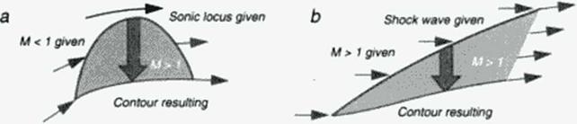
In the rheograph plane subsonic flow is separated from supersonic flow by the sonic locus, where U(s. t) = 0. Solving the model equations (64M67) for a transonic problem, where both types of flow (U < 0. U > 0) occur, therefore requires applying separate solution methods for both parts, with the need to have common data at the line U(s. t) = 0. For plane (p, = 0). transonic (p2 = 1/3) flow, solution to (64)-<65) is the first step, because it is decoupled from (66M67). Choosing U = s, V = t is just the simplest solution, without loosing generality of subsequently finding solutions X = X(s. t). Y a Y(s, t) to the linear system (66Ц67) in a second step. Creating a solution to both the subsonic pan and the supersonic part now requires prescribing data X*(t). Y*(t) along s = 0. This data prescription is equivalent to defining the sonic line and a distribution of flow directions along it in physical space (X. Y) The data are used as part of the boundary conditions to an elliptic problem in the subsonic domain (s £ 0» and as initial data for a hyperbolic problem in the supersonic domain (s 2 0). Figure 38a shows the direction of integrating the local supersonic flow pattern: with the complete sonic line given, supersonic marching must be performed in a cross-flow direction, leaving die given sonic line unchanged and obtaining an arc of the surface geometry as a result. This way an inverse approach results in the goal of obtaining a surface geometry compatible with a strongly controlled sonic line. In the 1970’s, techniques were developed to design transonic airfoils using this concept (84). A rheoelectric analog computer’ provided a very educational tool to understand also the background of Garabcdian’s method of complex characteristics to design shock-free airfoils (85). which was a mathematically elegant method but did not provide a lasting engineering know ledge base because of its complexity
It is only a small step to a quite different application of this inverse concept for local flow field integration: Replacing the sonic locus by an oblique shock wave, geometrically defined in a given (uniform or nonuniform) upstream supersonic flow, defines also post shock flow data as initial conditions for a cross-flow integration toward a contour streamline compatible w ith the oblique shock wave. Figure 38b shows this approach: a segment of supersonic flow bounded by the given shock wave, the resulting contour and an open exit illustrate ЫчЬ the commonality and the difference with the transonic design approach. Figure 38a. The supersonic application will be described in more detail in the next book chapter, while the following paragraphs of this chapter arc devoted to numerical design methods based on the transonic application.
|
Figure 38 Inverse design concepts in transonic and in supersonic flow. |