Regions of Significant 3D Effects
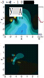
SYNCHRONIZED HOVERING, HIGH AOA – PRESENCE OF A PERSISTENT JET. As shown in region 1 in Figure 3.21d, the kinematics in this region corresponds to nearly synchronized hovering (i. e., including cases with slightly delayed or advanced rotation), low angular amplitude (high AoA), and larger plunging amplitudes. Figure 3.22 shows the time history of lift and vertical velocity contour plots at three time instants: in the forward stroke from the 2D simulation, in the symmetry plane of the 3D computation, and near the wingtip. It can be seen that there are two local maxima per stroke in 2D. The first peak is associated with the wake capture at the beginning of the
![]()
 |
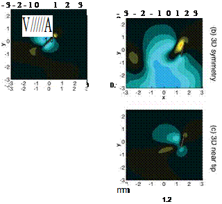 |
Figure 3.22. Instantaneous force history (2D: solid, red; 3D: broken, black) and vertical velocity contour plots at three time instants in the forward stroke for the synchronized rotation and high AoA (2ha = 3.0cm, aa = 45°, and <p = 90°): (a) 2D computation; (b) in the symmetry plane of 3D computation; (c) near the wing tip (z/c = 1.8).
stroke at t/T = 0.8. Between the two peaks, there is a local minimum referred to as a “wake” valley, which is caused by a combination of decreasing AoA and interaction with a pocket of downward momentum that takes the form of a persistent jet. As reported during the experimental studies of Freymuth [175], the jet develops as a result of a reverse Karman vortex street interacting with the downward momentum created by the wing as it translates. As the wing passes the jet, vortices are shed with an orientation that reinforces the downward momentum previously created by
 |
 |
-2-10 1 2 3
x
U2
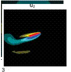
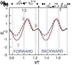
Figure 3.23. Time history of lift coefficients in a representative case in region 2; the advance rotation and low AoA (2ha = 4.0cm, aa = 80°, and <p = 120°), with the associated flow features. (a) Lift, (CL), during a motion cycle. Red-solid, 2D computation; black-dashed, 3D computation. (b) Kinematic schema of the flat plate motion. (c) Representative flow features at (1) t/T = 0.9, vertical velocity (u2) contours; (2) t/T = 1.0, vorticity contours; (3) t/T = 1.2, vertical velocity contour.
the wing. These vortices sustain the downward momentum, and they further entrain surrounding fluid to create a flow feature with which the wing then interacts during subsequent strokes. In 3D, the weaker downward momentum pocket does help generate lift compared with 2D, which can be confirmed in the instantaneous lift history at t/T = 0.9. In 2D, the persistent jet shows larger vertical velocity magnitude and is narrower. However, the weaker LEV has a negative effect on the lift. In the 2D case, the LEV is largely attached, and anchoring the LEV has no benefit. Overall, for this case, the 2D lift is better than the 3D counterpart. More generally, cases in region 1 as shown in Figure 3.21d have larger lift in 2D.
advanced rotation and low aoa – higher 3D lift. In region 2 as shown in Figure 3.21d, the kinematics is characterized by advanced rotation and a high angular amplitude. Figure 3.23 shows the time histories of lift and the associated flow
features for an advanced rotation case with a generally low AoA (2ha = 4.0cm, aa = 80°, and p = 120°). Right after the stroke reversal, the flat plate moves into the wake generated in the previous stroke. Because of the downwash in this wake (see also Fig. 3.23) and the low and decreasing AoA (Fig. 3.23b), lift drops. Note that the pocket of downward momentum encountered for these kinematics is not a persistent jet: the 3D case does not suffer the same drop in lift as the 2D case.
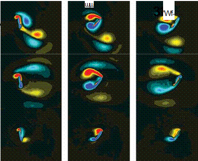
DELAYED ROTATION AND HIGH AOA – TIP VORTEX CAN ENHANCE LIFT. Region 3 is defined by the kinematics with delayed rotation, low angular amplitude (high AoA), and shorter plunging amplitudes. This region shows a significant impact from the TiVs. Figure 3.24 illustrates a delayed rotation case with high AoA (2ha = 2.0cm, aa = 45°, and p = 60°). The difference in the flow physics encountered due to 3D phenomena is noticeable. The main characteristics of the vortices, including their sizes, strengths, and movement, are distinctly different between 2D and 3D results. Not only is there a strong spanwise variation in the 3D flow but there is also little resemblance between the symmetry plane of the 3D and the 2D computations.
In 2D flow the pair of the large-scale vortices is noticeably closer to each other and the airfoil than in the 3D flow. The instantaneous lift coefficient for the two cases examined is illustrated in Figure 3.24; the 3D lift coefficient is generally higher than its 2D counterpart. With these kinematics patterns, the TiVs can interact with the LEV to form a lift-enhancement mechanism. This aspect is discussed next.
Figure 3.25 shows an iso-Q contour colored by rn3, the spanwise vorticity in forward stroke. In this fashion we can separate the rotation from the shear, via Q, which can be used as a measure of rotation; we can then obtain directional information with vorticity. The vortices shed from the leading and trailing edges are identified by red and blue colors, respectively, whereas the TiV is green. The role of the TiV in the hovering cases studied is particularly interesting. For the case presented in Figure 3.25 (delayed rotation) – the Q iso-surface colored with «3-vorticity, along with the spanwise distribution of CL due to pressure – the effects of the tip vortices become apparent. First, a low-pressure region at the wingtip favorably influences the lift. Second, the TiV anchors the large-scale vortex pair near the tip. At mid-span, however, the vortex pair has separated from the wing. This in turn drives the spanwise variation seen in the flow structures and force history.
Compared with an infinite wing, the TiVs cause additional mass flux across the span of a low-aspect-ratio wing, which helps push the shed vortex pair, from the leading edges and trailing edges, at mid-span away from one another. Furthermore, there is a spanwise variation in effective AoA induced by the downwash, which is stronger near the tip. Overall, the TiVs allow the vortex pair in their neighborhood of the tip to be anchored near the wing surface, which promotes a low-pressure region and enhances lift. The end result is an integrated lift value that departs considerably from the 2D value.
From the discussions in this section, it is clear that the kinematic motions have a significant impact on TiV formation and LEV/TEV dynamics. Interestingly, for many of the kinematic motions examined, the TiV force enhancement could be confined to lift benefits; that is, the resulting drag did not increase proportionally.
 |
|
Figure 3.24. Force history (2D: solid red, 3D: dash black) for a flapping cycle and z-vorticity contour plots at three time instants in the forward stroke for the delayed rotation and high AoA (2ha = 2.0cm, aa = 45°, and <p = 60°): (a) 2D computation; (b) in the symmetry plane of 3D computation; (c) near the wingtip (z/c = 1.8).
DELAYED ROTATION, LOW AOA, LOW AMPLITUDE – ABSENCE OF WAKE CAPTURE IN 3D.
The kinematics in region 4 is characterized by delayed rotation, large angular amplitude (or low AoA), and shorter plunging amplitude (see Fig. 3.21d). Note that the phase lag between the plunging and pitching motion is similar to that of previous sections, but the amplitude of both pitch and plunge differs. Figure 3.26 shows the time histories of lift from the 2D and the 3D computations, along with a schema for the kinematics as a representative case for region 4: 2ha = 2.0cm, aa = 80°, and = 60°. The largest discrepancy between 2D and 3D is seen around t/T = 0.9. Because the rotation is delayed, after the stroke reversal at t/T = 0.75 the flat plate creates rotational starting vortices to increase the lift, with its first peaks around t/T = 0.9. However, as shown in Figure 3.26, in the 2D case, the TEV shed in
the previous stroke interacts with the flat plate after the stroke reversal, thereby enhancing the lift by the wake-capture mechanism (t/T = 0.9). In contrast, for the 3D case, the shed LEV and the TEV repel from each other and from the path of the flat plate, such that after the stroke reversal, the wake capturing is absent. The first lift peak in the time history in Figure 3.26 is then only due to the rotational effects. So the diverging behavior of the vortices, observed for all delayed rotation cases, and the interaction of the vortices from the leading and trailing edges with the TiVs, play a central role as important 3D effects as described in the previous section.


