Our heavyweight helicopter equal in the world does not have
In Rostov started production of the most load-lifting rotary-wing car The Russian holding «Helicopt[...]

Everything about aircrafts and helicopters. News and events in aviation worldwide. Civil, transportation, military helicopters and airplanes.

Everything about aircrafts and helicopters. News and events in aviation worldwide. Civil, transportation, military helicopters and airplanes.

Everything about aircrafts and helicopters. News and events in aviation worldwide. Civil, transportation, military helicopters and airplanes.

Everything about aircrafts and helicopters. News and events in aviation worldwide. Civil, transportation, military helicopters and airplanes.


9.1 VELOCITY AND PRESSURE DISTRIBUTIONS
Aeromodelling has undergone a revolution since the time of F. W. Schmitz. Free flight models still operate close to critical Reynolds number conditions but radio controlled models, especially the larger sailplanes, high speed racers and aerobatic models are usually outside the danger area. Many such models fly quite successfully with profiles similar to the Clark Y or Gdttingen 796 and it is obvious that problems of sub-critical flow separation have been left behind. Part of the reason for this is that such models do not usually fly at very high angles of attack. As Schmitz’s results showed, a profile like the N-60 operated efficiently at a low angle of attack but stalled early even when operating, nominally, above its critical Re. The same thing was found on the Go 801, separation problems at high angles of attack did not entirely disappear until about Re 170,000. Modellers have put up with the premature stall of such profiles. Performance at higher speeds is quite good. The pylon racing model is in any case operating most of the time at Re’s quite comparable with those of full-sized sailplanes and even some light aeroplanes. Very great improvements in performance have been achieved in full-sized sailplanes, and some powered aircraft, by the use of so-called laminar flow profiles. The advantage in terms of saving skin friction are very large, especially at high speeds where profile drag becomes of major importance (Fig. 4.10). Early work in this area by the Low Speed Aerodynamics Research Association has been largely overlooked by modellers, but the aerofoils LDC2 and LDC3M produced were used on some models at the time, about 1948, when they first appeared.
As described in Chapter 3, on any wing, the boundary layer will be laminar at first near the leading edge, but will make a transition to turbulent flow when it reaches the critical boundary layer Re. The value of this critical Re will depend on the quality of the wing surface. Many full-sized aircraft have poor surfaces. Even if highly polished, there are waves and ripples in the skin caused by rivet tension and humps created by stiffeners and spars. It is very difficult to preserve laminar flow over such a wing for more than a few centimetres near the extreme leading edge, and even when great efforts are made to achieve an accurate profile, the large Reynolds number associated with the high flight speed and large wing chord, promotes early transition. The smallest defect in the surface, even a fly speck or the crushed body of an insect, can cause transition. For these and similar reasons designers of full-sized light aeroplanes have not been able to achieve all the benefits of low drag, laminar flow, and many still prefer to use relatively old-fashioned profiles. However, as the Reynolds number falls, the chances of preserving laminar flow over more of the wing increase. Small defects that, at higher velocities, cause transition,
may be over-ridden by the relatively more viscous boundary layer, and if wings can be made accurately, as they are in modem full-sized sailplanes, the aerodynamicists’ predictions, based on theoretical studies and wind tunnel tests, come true. The problem for modellers is the reverse of that for the turbulent flow aerofoils. At sub-critical Re, turbulators and protrusions caused by spars may improve performance by forcing transition in the boundary layer. Laminar flow models should seek to maintain profile accuracy at least as far back as the point where the boundary layer will make its transition naturally. The standard of precision required is, because of the low Re, less than that needed for the full-sized aircraft.
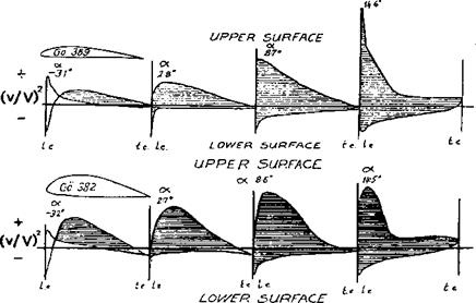
Providing the wing surface is smooth, a laminar boundary layer will tend to prevail as long as the speed of flow is rising under the influence of the low pressure area above the wing (Fig. 3.5). Behind the minimum pressure point the laminar flow persists for some distance but then a separation bubble forms and (providing super-critical Re prevails), the flow re-attaches as a turbulent boundary layer. In Figure 9.1 velocity measurements made on two wing profiles are shown. These show how the speed of flow over the upper and lower surfaces vary at different angles of attack. On the Gottingen 389, for example, at 2.8 degrees angle, the flow on the upper surface increases rapidly to a maximum within the first ten percent of the wing chord. Laminar flow will persist up to this point and a little way beyond it, but then transition will occur and turbulent, high drag flow covers most of the wing. At a lower angle of attack, -3.1 degrees, the maximum velocity point on the upper side is somewhat further back, but at higher angles it moves forward so that near the stall, at 14.6 degrees, the whole upper surface is in turbulent flow. Meanwhile, on the underside the velocity peak of the upper surface is opposed by a velocity decrease close to the leading edge, and thereafter the air accelerates towards the trailing edge. Transition
|
Fig. 9.1 Velocity profiles of two G6ttingen aerofoils OC
|
|
|
will already have taken place and the boundary layer will be turbulent. At the more negative angles of attack, the roles of upper and lower surfaces are reversed as the wing begins to ‘lift’ downwards.
The Gottingen 382 profile is a thicker version of the 389, but the velocity measurements show important differences. At 2.7 degrees angle, the velocity maximum on the upper side is about ten percent further aft than on the thinner profile, and even near the stall there is a likelihood for laminar flow back to about ten percent before the velocity decrease causes transition.
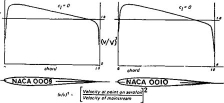
The details of the velocity of airflow over a wing depend on both its thickness form and its camber. The typical, pre-1940 aerofoils of Figure 9.1 and others of the same vintage, such as the Clark Y, N-60, etc. were designed around what was then thought to be the ideal form for any streamlined body. The same basic shape, thickened or thinned appropriately, was used for strut fairings, streamlined wires, tailplane and fin profiles, wheel spats and whole airship hulls. Typical ordinates are given in Figure 9.2 which refer to the NACA ‘four digit’ aerofoils. The velocity distribution graphs given with the profiles show that at zero angle of attack, the velocity peak (and hence minimum pressure point) on both surfaces is reached at about ten percent of the chord. A short distance aft of this, transition to turbulent flow occurs. Cambering changes this basic feature only slightly; such profiles are fundamentally incapable of preserving laminar airflow over much of the wing.