Our heavyweight helicopter equal in the world does not have
In Rostov started production of the most load-lifting rotary-wing car The Russian holding «Helicopt[...]

Everything about aircrafts and helicopters. News and events in aviation worldwide. Civil, transportation, military helicopters and airplanes.

Everything about aircrafts and helicopters. News and events in aviation worldwide. Civil, transportation, military helicopters and airplanes.

Everything about aircrafts and helicopters. News and events in aviation worldwide. Civil, transportation, military helicopters and airplanes.

Everything about aircrafts and helicopters. News and events in aviation worldwide. Civil, transportation, military helicopters and airplanes.


Dunng recent years a number of computational methods for designing 2D airfoils and 3D w ings in the transonic regime have been developed. Among them arc inverse methods, with the task to find airfoil or wing shapes for a prescribed pressure distribution. These latter methods are reviewed in chapter 10 of this book. The aim in the present chapter is only to illustrate some relations between gasdynamic properties of compressible flow and some practical consequences for 2D and 3D surface geometry quality.
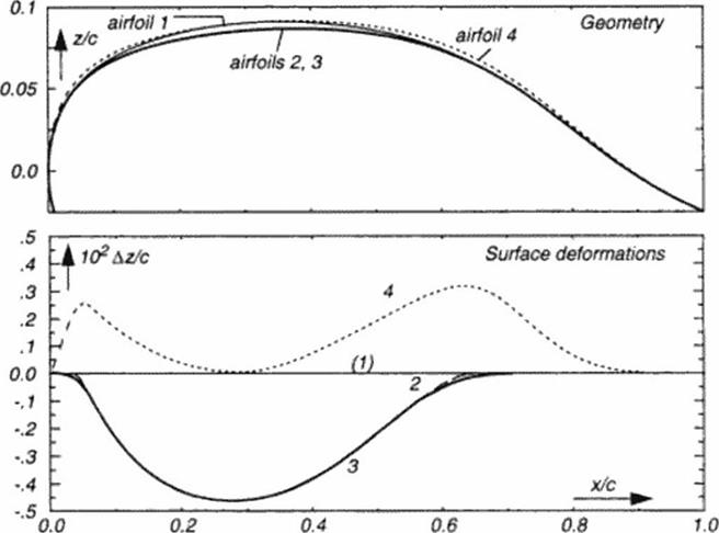
In practical aerodynamics frequently a given configuration and its components may be modified only locally because of structural and other constraints. The FG design method is a practical tool if small local changes are allowed on the suction surface of a lifting wing: thickness distribution of a typical transport aircraft wing section may be reduced along a limited portion along chord less than half a percent to obtain improved aerodynamic efficiency up to 15 percent! Improvements also may he obtained for sections with local thickness added to the given geometry. To illustrate this, a series of simple design modifications to the thick airfoil of Figure 40 was carried out and is outlined in Figure 42 and Figure 43:
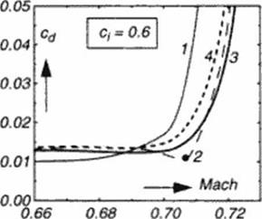
Following a FG computation (Figure 41). the method of characteristics defines a new section geometry on the upper surface ( see the graphics of Figure 40). Contour differences are shown in Figure 42: given (baseline) wing section 1 and resulting section 2 differ by a Az distribution. subtracted from the baseline. This Az is smoothly shaped as a bump’ function extending from the some expansion to the recompression location. A comparison of the aerodynamic properties for the baseline (1) and the new airfoil (2) is show n in Figure 43. Drag rise and airfoil polar obtained by CFD analysis (931 are illustrated. Related airfoil geometries with similar efficiency improvements may be obtained for mathematical approximations of the whole sub – traded bump or its key features: amplitude and crest curvature. An airfoil ‘3’ is obtained for a bump function with only smoolhened (extended) start and end ramps, resulting in a slight loss in the Lift/Drag (L/D) ratio at design conditions, but with improved off-design performance, reducing ‘drag creep’ at lower Mach numbers. Airfoil ‘4’ is obtained by adding a dual bump (now locally enlarging thickness everywhere along chord), modelling local curvature at x/c – 0.3 to be equivalent to the design modification. The resulting airfoil has still improved aerodynamic efficiency compared to the baseline These latter added bump function may be combined with the concept of more local shape modifications like those used tor influencing viscous interaction at the shock location (94J.
There arc various ways to calibrate geometrical models like the above used bump functions from observ ed phenomena like some surface geometries. The method of characteristics for 2D How is the straightforward exact approach. Analysis of How stream tube displacement requirements lead to even faster methods [951 which are suitable for 3D w ing design.
|
|
|
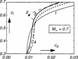
Drag rise for constant lift and drag polar at constant Mach number, for above 4 airfoils. Rc = 20 MOL (MSES (931 analysis!
7.2 Conclusion
In this chapter the attempt was made to illustrate some ideas which have been used and still seem to have innovative potential for the development of aerodynamic design tools. A refined analysis of inviscid How phenomena is earned out by mapping into a suitable work space, resulting in mathematical models for local and asymptotic behavior of compressible flows. These models may be used for CFD code validation and also should be i»bserved when prescribing target How conditions in inverse design approaches
Geometric boundary conditions, shock waves and the singularities connected with some llow conditions are shown to be strongly interacting, the know ledge about these phenomena may be used for aerodynamic design concepts. These lay ground for an inverse flow construction principle with applications to transonic as well as to supersonic flow. Numerical methods may be manipulated and recombined for obtaining airfoils and wings with improved aerodynamic efficiency and concepts for the development of novel flow control techniques could be encouraged by theoretical results.
Supersonic and hypersonic How models derive from these principles, too. and will be used in the following book cliapter for the design of advanced wavenders.
Numerical analysis and models to control gasdynamics result in a more detailed knowledge base about the shaping of flow boundaries, which translates into selecting a set of mathematical deformation functions for the optimization or adaptation of given baseline configurations. Being guided by the quality of the observed flow phenomena strongly helps to keep the number of control parameters for these functions small, as w ill be demonstrated in book chapter 9