Our heavyweight helicopter equal in the world does not have
In Rostov started production of the most load-lifting rotary-wing car The Russian holding «Helicopt[...]

Everything about aircrafts and helicopters. News and events in aviation worldwide. Civil, transportation, military helicopters and airplanes.

Everything about aircrafts and helicopters. News and events in aviation worldwide. Civil, transportation, military helicopters and airplanes.

Everything about aircrafts and helicopters. News and events in aviation worldwide. Civil, transportation, military helicopters and airplanes.

Everything about aircrafts and helicopters. News and events in aviation worldwide. Civil, transportation, military helicopters and airplanes.


One of the problems that developers of wing-in-ground-effect vehicles have to solve is related to necessity to reduce the power required for detaching the craft from water. An efficient way to facilitate takeoff consists of blowing air under the main wing of the craft from special engines. This mode of vehicle operation is often called power augmentation or, briefly, PAR. Power augmentation provides additional dynamic head to support the vehicle at small speed and alleviates hydrodynamic loads due to the impact of waves upon the structure of the craft. From the viewpoint of aerodynamics and hydrodynamics, the problem of power-augmented takeoff is extremely complicated. It features the interaction of turbulent jets with the vehicle and water surface, the resulting spray effects, and the transient motion of the vehicle. In what follows, only very simplified models of power-augmented flows will be considered for a lifting system moving very close to the underlying surface.
When modelling the aerodynamics of wing-in-ground-effect vehicles in regimes of takeoff and transition to cruise by using power augmentation of the main lifting system, different schemes of the flow of air blown from the upstream PAR engines onto a wing may be adopted. Some of these schemes are depicted in Figs. 8.1-8.3.
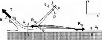
The first scheme of power-augmented flow suggests that the suction force at the leading edge is not realized and that interaction of the exhaust from the engines with this edge manifests itself in the generation of a reentrant jet, oriented at a certain angle /?j with respect to the downstream direction. It can be assumed that the far-held direction of the jet is subject to the requirement of the conservation of total momentum. The scheme with the reentrant jet was used by Gallington et al. [154, 156] in the analysis of the efficiency of power-augment at ion regimes. These authors considered simplified cases of how around a hat plate at zero incidence and dehected hap, assuming that there is no leakage from the gaps under the endplates.
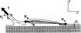
The second scheme of PAR flow can be introduced on an assumption that the suction force is completely realized, and, moreover, that part of air jets from the upstream engines hows along the suction surface of the wing and continues to propagate downstream without separating from the upper surface of the hap. The argument behind the second scheme, shown in
K. V. Rozhdestvensky, Aerodynamics of a Lifting System in Extreme Ground Effect © Springer-Verlag Berlin Heidelberg 2000
|
Fig. 8.1. Scheme (1) of power-augmented flow with a reentrant jet, [153, 154, 155]. |
|
Fig. 8.2. Scheme (2) of power-augmented flow with the realization of a suction force and unseparated streamlines along the upper surface of the wing and the flap. |
Fig. 8.2, is certain experimental evidence that the jets envelop the rounded leading edge due to the Coanda effect (see Krause [156]).[41]
This scheme does not seem to be completely plausible for takeoff regimes at small relative ground clearances, when sudden decceleration of the turbulent jets generated by the upstream engines and rather slow motion of air in the channel under the wing is observed. These circumstances together with the fact that the flap deflection angles at takeoff are quite considerable (of the order of 20-30°) does not give a basis for assuming nonseparated flow past the suction surface of the wing.
At the same time, a well-known property of the Coanda effect, especially for relatively thin upper part of a bifurcating jet, to delay separation on the upper surface of the wing, does not allow us to reject consideration of flow models with the realization of the suction force.
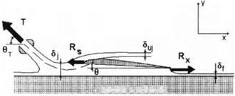
In this connection the third scheme of power-augmented flow shown in Fig. 8.3 may be considered. This scheme may be based on a suggestion that the Coanda effect forces part of the bifurcating jet to envelop the leading edge of the wing, but for a certain combination of system parameters separation
 ! – к ІІиШИІІІІІ ІмШШІІІИЯ
Fig. 8.3. Scheme (3) of power-augmented flow with the partial realization of the suction force and the jet leaving the rounded leading edge (Coanda PAR flow model).
of the jet from suction surface of the wing may occur at some angle /3sep. In the third scheme it is assumed that the flow past the flap is separated.
To develop a description of power-augmented air flow past a vehicle in the extreme ground effect, it is appropriate to use the method of matched asymptotic expansions, taking the relative ground clearance h as a basic small parameter, i. e., treat the PAR problem in a fashion, which has been adopted throughout this book. Then the channel flow under the wing with small gaps under the endplates can be assumed to be described with a certain degree of adequacy by equation (4.53) or (in the steady case) by equation (4.65). The solution of these equations enables us to determine both the span-averaged velocity and pressure and, eventually, the lift, moment and induced drag. To calculate the flow parameters near leading and trailing edges and associated suction force and ideal pressure drag on the flap, it is necessary to consider the corresponding local flow problems. Local flow formulations can be used, e. g., for determining the appropriate deflection of the leading edge flap for shock-free entry of the flow and analysis of other possibilities of controlling the efficiency of cruise and PAR modes of performance of wing-in-ground – effect vehicles. A set of relevant local leading edge and trailing edge flow problems for power-augmented regimes is summarized in Figs. 8.4-8.10. In what follows, solutions are presented of selected local flow problems.