
Our heavyweight helicopter equal in the world does not have
In Rostov started production of the most load-lifting rotary-wing car The Russian holding «Helicopt[...]

Everything about aircrafts and helicopters. News and events in aviation worldwide. Civil, transportation, military helicopters and airplanes.

Everything about aircrafts and helicopters. News and events in aviation worldwide. Civil, transportation, military helicopters and airplanes.

Everything about aircrafts and helicopters. News and events in aviation worldwide. Civil, transportation, military helicopters and airplanes.

Everything about aircrafts and helicopters. News and events in aviation worldwide. Civil, transportation, military helicopters and airplanes.


The direct and coupled damping derivatives are collectively one of the most important groupings in the system matrix. Primary damping derivatives reflect short-term, small and moderate amplitude, handling characteristics, while the cross-dampings play a dominant role in the level of pitch-roll and roll-pitch couplings. They are the most potent derivatives in handling qualities terms, yet because of their close association with short-term rotor stability and response, they can also be unreliable as handling parameters. We shall discuss this issue later in Chapter 5 and in more detail in Chapter 7, but first we need to explore the many physical mechanisms that make up these derivatives. There has already been some discussion on the roll damping derivative in Chapter 2, when some of the fundamental concepts of rotor dynamics were introduced. The reader is referred back to the Tour (Section 2.3) for a refresher.
Taking the pitch moment as our example for the following elucidation, we write the rotor moment about the centre of mass in the approximate form
Mr = — Nb Ke + Th^j flic (4.81)
where Kp is the flapping stiffness, T the rotor thrust and h r the rotor vertical displacement from the centre of mass. In this simple analysis we have ignored the moment due to the in-plane rotor loads, but we shall discuss the effects of these later in this section. The rotor moment therefore has two components – one due to the moment of the thrust vector tilt from the centre of mass, the other from the hub moment arising from real or effective rotor stiffness. Effective stiffness arises from any flap hinge offset, where the hub moment is generated by the offset of the blade lift shear force at the flap hinge. According to eqn 4.81, the rotor moment is proportional to, and hence in phase with, the rotor disc tilt (for the centre-spring rotor). The relative contributions of the two components depend on the rotor stiffness. The hub pitch moment can be expanded in the form (see eqns 3.104, 3.105)
Mh = ~NbKep1c = – N & lp (k2p – 1) P1c (4.82)
and the corresponding roll moment as
Lh = – NbKjep1s = –2 & Ip (k} – 1) P1s (4.83)
The hub moment derivatives can therefore be derived directly from the flapping derivatives. Since the quasi-steady assumption indicates that the disc tilt reaches its steady – state value before the fuselage begins to move, the flap derivatives can be obtained from the matrix in eqn 3.72; thus, in hover, where the flap effects are symmetrical,
|
Эв1с |
dft1s |
1 |
(So + Y) |
(4.84) |
|
d q |
9 p |
1 + Se |
||
|
dfitc |
dPs |
1 |
(Se 7 – 0 |
(4.85) |
|
9 p |
d q |
1 + Se |
The Stiffness number Sp is given by eqn 4.59.
The variation of the flap damping derivatives in eqns 4.84 and 4.85 with the fundamental stiffness and Lock parameters has been discussed in Chapter 2 (see Figs 2.21 (b) and (c)). For values of Stiffness number up to about 0.4, corresponding to the practical limits employed in most current helicopters, the direct flap derivative is fairly constant, so that helicopters with hingeless rotors flap in very much the same way as helicopters with teetering rotors. The Lock number has a much more dramatic effect on the direct flap motion. Looking at the coupling derivatives, we can see a linear variation over the same range of Stiffness number, with rotors having low Lock number experiencing a reversal of sign. This effect is manifested in the Bo105 helicopter, as illustrated in the derivative charts of the Appendix, Section 4B.2, where the Lock number of 5 and Stiffness number of about 0.4 result in a practical cancelling of the rolling moment due to pitch rate Lq. The rotor Lock number is critically important to the degree of pitch-roll coupling.
From the theory of flap dynamics derived in Chapter 3, we can explain the presence of the two terms in the flap derivatives. The primary mechanism for flap and rotor damping derives from the second term in parenthesis in eqn 4.84 and is caused by the aerodynamic moment generated by the flapping rate (at azimuth positions 90° and 270°) that occurs when the rotor is pitching. The disc precesses as a result of the aerodynamic action at these azimuth stations, and lags behind the rotor shaft by the angle (16/уй) x pitch rate. The primary mechanism for coupling is the change in one-per-rev aerodynamic lift generated when the rotor pitches or rolls (second term in eqn 4.85), adding an effective cyclic pitch. Both effects are relatively insensitive to changes in rotor stiffness. The additional terms in Sp in eqns 4.84 and 4.85 arise from the fact that the flap response is less than 90° out of phase with the applied aerodynamic load. The direct aerodynamic effects, giving rise to the longitudinal and lateral flapping, therefore couple into the lateral and longitudinal flapping respectively. The effect on the coupling is especially strong since the direct flap derivative provides a component in the coupling sense through the sign of the phase angle between aerodynamic load and flap response.
Combining the flap derivatives with the hub moments in eqns 4.82 and 4.83, we can derive approximate expressions for the rotor hub moment derivatives, in seminor – malized form, for small values of Sp:
The hub moment derivatives are therefore scaled by the Stiffness number, but otherwise follow the same behaviour as the flap derivatives. They also increase with blade number and rotorspeed. It is interesting to compare the magnitude of the hub moment with the thrust tilt contribution to the rotor derivatives. For the Lynx, the hub moment represents about 80% of the total pitch and roll damping. For the Puma, the fraction is nearer 30% and the overall magnitude is about 25% of that for the Lynx. Such is the powerful effect of rotor flap stiffness on all the hub moment derivatives reflected in the values of Sp for the Lynx and Puma of 0.22 and 0.044 respectively. As can be seen from the derivative charts in the Appendix, Section 4B.2, except for the pitch damping, most of the rate derivatives discussed above are fairly constant over the speed range, reflecting the insensitivity with forward speed of rotor response to equivalent cyclic pitch change. The pitch damping derivative Mq also has a significant stabilizing contribution from the horizontal tailplane, amounting to about 40% of the total at high speed.
 |
|
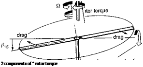
Before leaving the roll and pitch moment derivatives, it is important that we consider the influence of the in-plane rotor loads on the moments transmitted to the fuselage. In our previous discussion of the force derivatives Xq and Yp, we have seen how the ‘Amer effect’ reduces the effective rotor damping, most significantly on teetering rotors in low-thrust flight conditions. An additional effect stems from the orientation of the in-plane loads relative to the shaft when the rotor disc is tilted with one-per-rev flapping. The effect is illustrated in Fig. 4.21, showing the component of rotor torque oriented as a pitching moment with lateral flapping (the same effect gives a rolling moment with longitudinal flapping). The incremental hub moments can be written in terms of the product of the steady torque component and the disc tilt; hence, for four-bladed rotors
Fig. 4.21 Source of rotor hub couple due to inclination of rotor torque to the shaft
These moments will then combine with the thrust vector tilt and hub moment to give the total rotor moment. To examine the contribution of all three effects to the derivatives, we compare the breakdown for the Puma and Lynx. The Helisimpredicted hover torque for the Puma and Lynx work out at about 31 000 N m and 18000 N m respectively. The corresponding rotor thrusts are 57 000 N and 42 000 N and the effective spring stiffnesses 48 000 N m/rad and 166 000 N m/rad. The resultant derivative breakdown can then be written in the form
![]()
Lynx
![]() дв1с dB1s дв1с dB1s
дв1с dB1s дв1с dB1s
Mp = -6.62— + 0.46— Mp = -27.82— + 0.66—
p d p dp p dp d p
The effect of the torque moment on the direct damping derivative is therefore negligible. In the case of the coupling derivative, the effect appears to be of concern only for articulated rotors, and then only for rotors with very light blades (see the low Lock number cases in Figs 2.21(b) and (c)).
The derivatives Nr, Lr, Np
The final set of rate derivatives have little in common in terms of their physical makeup but share, along with their ‘big brother’ Lp, the property of having a primary influence on the character of the lateral/directional stability and control characteristics of the helicopter. We begin with a discussion of the yaw damping derivative Nr. In our previous discussion of the force derivatives, we rather dismissed the sideforce due to yaw rate Yr, since the inertial effect due to forward speed (Uer) was so dominating. The aerodynamic contribution to Yr, however, is directly linked to the yaw damping and is dominated by the loads on the tail rotor and vertical fin. Assuming that these components are at approximately the same location, we can write the yaw damping as
Nr ~ – It-r^Yr (4.94)
hz
In the hover, our theory predicts that Nr is almost entirely due to the tail rotor, with a numerical value of between -0.25 and -0.4, depending on the tail rotor design parameters, akin to the effect of main rotor design parameters on Zw (see Table 4.2). The low value of yaw damping is reduced even further (by about 30%) by the effect of the mechanical S3 coupling built into tail rotors to reduce transient flapping. The fin ‘blockage’ effects on the tail rotor can reduce Nr by another 10-30% depending on the separation and relative cover of the tail rotor from the fin. Yaw motion in the hover is therefore very lightly damped with a time constant of several seconds.
In low-speed manoeuvres the effect of the main rotor downwash over the tail boom can have a strong effect on the yaw damping. The flow inclination over the tail boom can give rise to strong circulatory loads for deep, slender tail booms. This effect has been explored in terms of tail rotor control margins in sideways flight (Refs 4.9, 4.16 and 4.17), and the associated tail boom loads in steady conditions, from which we
can deduce the kind of effects that might be expected in manoeuvres. The magnitude of the moment from the sideloads on the tail boom in a yaw manoeuvre depends on a number of factors, including the strength and distribution of main rotor downwash, the tail boom ‘thickness ratio’ and the location of any strakes to control the flow separation points (Ref. 4.16). A fixed strake, located to one side of the tail boom (for example, to reduce the tail rotor power requirement in right sideways flight), is likely to cause significant asymmetry in yaw manoeuvres. Main rotors with low values of static twist will have downwash distributions that increase significantly towards the rotor tips, leading to a tail boom centre of pressure in manoeuvres that is well aft of the aircraft centre of mass. The overall effect is quite complex and will depend on the direction of flight, but increments to the yaw damping derivative could be quite high, perhaps even as much as 100%.
As forward speed increases, so does the yaw damping in an approximately proportional way up to moderate speeds, before levelling off at high speed, again akin to the heave damping on the main rotor. The reduced value of Nr for the Puma, compared with Lynx and Bo105, shown in Appendix 4B, stems from the low fin effectiveness at small sideslip angles discussed earlier in the context of the weathercock stability derivative Nv. For larger sideslip excursions the derivative increases to the same level as the other aircraft.
One small additional modifying effect to the yaw damping is related to the rotor – speed governor sensing a yaw rate as an effective change in rotorspeed. At low forward speeds, the yaw rate can be as high as 1 rad/s, or between 2 and 4% of the rotorspeed. This will translate into a power change, hence a torque change and a yaw reaction on the fuselage serving to increase the yaw damping, with a magnitude depending on the gain and droop in the rotorspeed governor control loop.
Np and Lr couple the yaw and roll DoFs together. The rolling moment due to yaw rate has its physical origin in the vertical offset of the tail rotor thrust and vertical fin sideforce from the aircraft centre of mass. Lr should therefore be positive, with the tail rotor thrust increasing to starboard as the aircraft nose yaws to starboard. However, if the offsets are small and the product of inertia Ixz relatively high, so that the contribution of Nr to Lr increases, Lr can change sign, a situation occurring in the Lynx, as shown in the derivative charts of the Appendix, Section 4B.2. The derivative Np is more significant and although the aerodynamic effects from the main and tail rotor are relatively small, any product of inertia Ixz will couple the roll into yaw with powerful consequences. This effect can be seen most clearly for the Lynx and Bo105 helicopters. The large negative values of Np cause an adverse yaw effect, turning the aircraft away from the direction of the roll (hence turn). In the next section we shall see how this effect influences the stability characteristics of the lateral/directional motion. Before leaving Np and the stability derivatives however, it is worth discussing the observed effect of large torque changes during rapid roll manoeuvres (Refs 4.18, 4.19). On some helicopters this effect can be so severe that overtorquing can occur and the issue is given attention in the cautionary notes in aircrew manuals. The effect can be represented as an effective Np. During low – to moderate-amplitude manoeuvres, the changes in rotor torque caused by the drag increments on the blades are relatively benign. However, as the roll rate is increased, the rotor blades can stall, particularly when rolling to the retreating side of the disc (e. g., a roll rate of 90o/s will generate a local incidence change of about 3o at the blade tip). The resulting transient rotor torque change can now be significant and lead to large demands on the engine. The
situation is exacerbated by the changes in longitudinal flapping and hence pitching moment with roll rate as the blades stall. Within the structure of the Level 1 Helisim model, this effect cannot be modelled explicitly; a blade element rotor model with nonlinear aerodynamics is required. The nonlinear nature of the phenomenon, to an extent, also makes it inappropriate to use an equivalent linearization, particularly to model the onset of the effect as roll rate increases.
