
Our heavyweight helicopter equal in the world does not have
In Rostov started production of the most load-lifting rotary-wing car The Russian holding «Helicopt[...]

Everything about aircrafts and helicopters. News and events in aviation worldwide. Civil, transportation, military helicopters and airplanes.

Everything about aircrafts and helicopters. News and events in aviation worldwide. Civil, transportation, military helicopters and airplanes.

Everything about aircrafts and helicopters. News and events in aviation worldwide. Civil, transportation, military helicopters and airplanes.

Everything about aircrafts and helicopters. News and events in aviation worldwide. Civil, transportation, military helicopters and airplanes.


 |
In Figure 9.5 is shown a typical curve of profile drag plotted against ci for any of the NACA 6 series aerofoils. At the design ci, drag is much lower than for an orthodox or old – fashioned section. On either side of this value there is a low drag range or ‘bucket’ in the graph, so that small departures from the ideal operating conditions cause no change in profile drag coefficient At either side of the low drag bucket, on one surface or another, the velocity distribution changes and the boundary layer becomes turbulent, with an associated sharp rise in drag. In the NACA designations of these aerofoils, the third digit,
of thick and thin profiles
 |
usually written as subscript thus: NACA 643418, indicates the width of the low drag bucket, in this case 0.3 ci on either side of the ideal designed value for the profile. A profile with the subscript 3 as above, designed for a ci of 0.4, will work efficiently at c) down to 0.1 and up to 0.7. (Note, however, that constant drag coefficient does not mean constant drag force – the higher speed associated with lower Cl of the wing increase drag force at a constant Cd – see Chapter 2.) The fourth digit of the aerofoil number gives the design ideal lift coefficient, in tenths, and the final two figures give the profile thickness as a percentage of the chord.
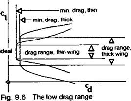
As already noted from the velocity profiles of the thick profiles of Figure 9.3, favourable flow conditions are preserved on thicker aerofoils over a greater range of ci than on thin ones. The absolute minimum drag of a thick profile is slightly more than for a thin section of similar camber, but the drag bucket of the thick profile is wider. This is indicated in Figure 9.3. Such a thick wing has a wider speed range, and, in the case, for example, of a racing model, will be less affected by slight inaccuracies of flying, and less slowed down in steep turns, than a model with thin wing and higher maximum speed straight and level.
As the Reynolds number is reduced, so long as flow remains super-critical (i. e. reattachment after the separation bubble), the natural tendency for laminar flow to persist shows up. The minimum drag of the laminar flow profile is slightly higher (because the relative viscosity of the air at low speeds is greater compared with the density-speed – chord factors), but the boundary layer, after passing the maximum velocity point on the wing, remains laminar for a greater distance and this has the effect of widening the drag bucket slightly. The result is shown diagrammatically in Figure 9.6.


