Our heavyweight helicopter equal in the world does not have
In Rostov started production of the most load-lifting rotary-wing car The Russian holding «Helicopt[...]

Everything about aircrafts and helicopters. News and events in aviation worldwide. Civil, transportation, military helicopters and airplanes.

Everything about aircrafts and helicopters. News and events in aviation worldwide. Civil, transportation, military helicopters and airplanes.

Everything about aircrafts and helicopters. News and events in aviation worldwide. Civil, transportation, military helicopters and airplanes.

Everything about aircrafts and helicopters. News and events in aviation worldwide. Civil, transportation, military helicopters and airplanes.


The loading on a helicopter blade is highly concentrated in the region of the tip, as has been seen (Figure 2.28). It is unlikely that a plain rectangular planform (a typical example is shown in Figure 6.6) is the optimum shape for the task of carrying this load and consequently investigations into tip design are a feature of modern aerodynamic research. Figure 6.8 shows the main rotor blade tip of the Merlin helicopter, which is the BERP planform with anhedral added (note the provision for picketing the blade and the leading edge erosion strip).
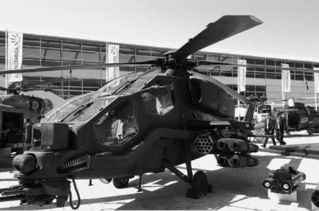
Figure 6.9 shows the main rotor blade tip of an Agusta Westland A129 variant. Since resultant velocities in the tip region on the advancing blade are close to Mach 1.0, it is natural to enquire whether sweepback can be incorporated to delay the compressibility drag rise and
|
|
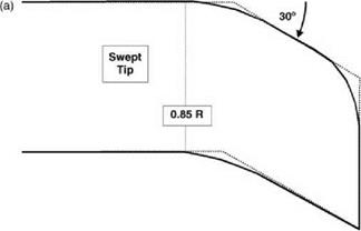
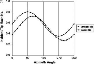
thereby reduce the power requirement at a given flight speed or alternatively raise the maximum speed attainable. The answer is not so immediately obvious as in the case of a fixed wing, because a rotor blade tip which at one moment is swept back relative to the resultant airflow, in the next moment lies across the stream. In fact, however, the gain from sweepback outweighs the loss, as is indicated in a typical case by Wilby and Philippe [8] (Figures 6.10a and b): a large reduction in Mach number normal to the leading edge is obtained over the rear half of the disc, including a reduction in maximum Mach number of the cycle (near C = 90°), at the expense of a small increase in the forward sector (C = 130° to 240°). Reductions in power required were confirmed in the case shown.
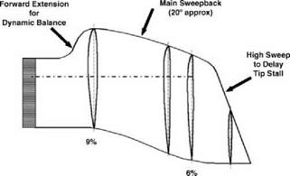
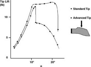
Shaping the blade tip can also be used to improve the stalling characteristics of the retreating blade. A particular all-round solution devised by Agusta Westland Helicopters is pictured in Figure 6.11. The principal features are:
• approximately 20° sweepback of the outboard 15% of blade span;
|
|
|
Figure 6.10 (a) Swept tip geometry. (b) Variation of Mach number normal to leading edge for straight and swept tips (after Wilby and Phillippe) |
|
Figure 6.11 Agusta Westland development blade tip (BERP) (Courtesy Agusta Westland) |
|
Figure 6.12 Wind tunnel results (non-oscillating) showing large advantage in stalling angle for Agusta Westland BERP tip (Courtesy Agusta Westland) |
• a forward extension of the leading edge in this region, to safeguard dynamic stability;
• a sharply swept outeredge topromote controlled vortex separation and thereby delay the tip stall.
Wind tunnel tests (static conditions) showed this last effect to have been achieved in remarkable degree (Figure 6.12). Subsequently the tip proved highly successful in flight and was used on a version of the Lynx helicopter which captured the world speed record (see Chapter 7).