Our heavyweight helicopter equal in the world does not have
In Rostov started production of the most load-lifting rotary-wing car The Russian holding «Helicopt[...]

Everything about aircrafts and helicopters. News and events in aviation worldwide. Civil, transportation, military helicopters and airplanes.

Everything about aircrafts and helicopters. News and events in aviation worldwide. Civil, transportation, military helicopters and airplanes.

Everything about aircrafts and helicopters. News and events in aviation worldwide. Civil, transportation, military helicopters and airplanes.

Everything about aircrafts and helicopters. News and events in aviation worldwide. Civil, transportation, military helicopters and airplanes.


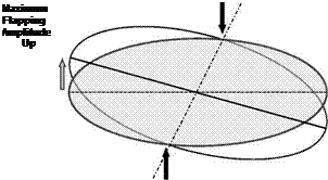
The phenomenon of gyroscopic precession is somewhat esoteric but it plays an important influence on tail rotor performance. To a first look, gyroscopic precession seems to disobey what is a natural understanding of the effect of moments on a body. The simple toy of a spinning top placed on a small tower seems to defy gravity. Instead of falling to the ground, it moves around a vertical axis only slowly leaning further and further, spiralling towards the ground plane on which the tower is standing. Figure 6.20 shows the top in question.
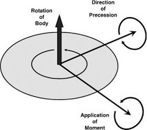
Using the right-hand rule, the top rotation and angular momentum are shown aligned with the spindle. The direction of the gravitational moment on the top is shown pointing to the right. The basic law is that the moment gives the rate of change of angular momentum. Hence the effect of gravity (and the reaction from the tower) will cause the angular momentum of the top to move in the same direction and thus the top rotates around the vertical axis in the precessional direction as shown. In Figure 6.21, the essential requirement is shown.
With reference to the rotational direction of the spinning body, the precessional rotation follows the applied moment by 90°.
The apparent avoidance of gravity is not a miracle, it just requires the moments and rotational directions to be expressed by vectors and then the standard laws apply – which they must!
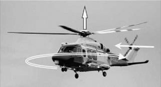
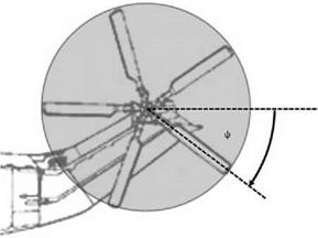
The tail rotor will encounter precession principally in the spot turn manoeuvre. This is where the helicopter is in hover and, by applying an increase/decrease in tail rotor thrust, spins about an axis along the main rotor shaft. This is illustrated in Figure 6.22, where the aircraft is rotating nose-left.
The tail rotor disc will have to rotate about a vertical axis, even though it is rotating about the rotor shaft. In order for this to happen, the rotor must have an appropriate precessional moment applied to it – as described in Figure 6.23.
|
Figure 6.21 Precessional moment |
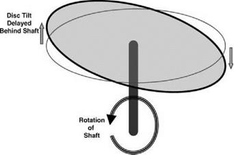
This moment cannot be achieved by any other means than aerodynamic, since the blades are not rigidly attached to the rotor shaft. With a fixed collective pitch and no cyclic pitch provision, the only way a moment can be generated is by blade flapping. It is important to note that lift variation is dependent on blade flapping velocity and not flapping displacement. Bearing this in mind, Figure 6.24 shows a rotor, where there is a disc tilt caused by a flapping displacement. The flapping velocities can be seen to be 90° out of phase with the flapping displacement. We therefore have two phase angle changes to consider, which results in the rotation of a rotor about an axis in the plane of rotation as shown in Figure 6.25. The rotor disc flaps in a direction lagging behind the shaft movement – the two 90° phase angles sum to give a total phase change of 180°.
|
|
|

 |
It can be shown that the rotation of a tail rotor about a vertical axis will generate a disc tilt of magnitude:
![]() Disc tilt
Disc tilt
(6.10)
 |
|
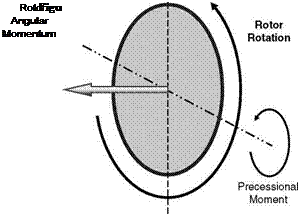
With the azimuth definition shown in Figure 6.26, a spot turn manoeuvre will cause a disc tilt which can be seen to be of a variety.
Figure 6.24 Relationship between flapping amplitude and flapping velocity
|
If we also consider the provision of pitch-flap coupling via a S3 hinge, the incidence of a typical blade is:
= 00-b-b tan S3- 7ZD
 |
The values of VZ and VJ are to be assumed constant over the rotor disc. Hence the Vz term will represent the value at the centre of the rotor. The VJ value will be defined by actuator disc theory
in climb at the appropriate value of VZ. We define the flapping angle and velocity as:
![]() b = a0—a cos ф b’ = a sin ф
b = a0—a cos ф b’ = a sin ф
 |
|
from which we find from (6.11):
 |
||
from which we must have:
![]()
![]() VZD
VZD
a = 60—a0 tan d3—a1sec d3 • sin^—d3)———
Or
This will have an extreme value of:
a = 60—a0 tan d3 + a1 sec d3 — —Z—
Or
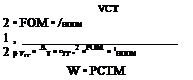
If the blade is not to experience stall – taking the blade tip, as it has the highest Mach number – the collective pitch will be limited by this condition giving the stall incidence, aS, that is:
= as + a0 tan 03— a sec 03 + (mZ + 1i) Now the rotor thrust will be given by:
 |
which becomes:
The normalized climb rate is given by:
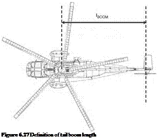
_ F • ^BOOM
Fz = VTT
. (6.24)
_ ^BOOM
Ot Rt
Using momentum theory we obtain:
Ctt = 41i(mZ + li) (6.25)
For the limiting case where the extreme rotor blade tip is at the point of stall, we must have from (6.21) and (6.25):
CTT Max = 41i Max (Fz + Ai Max)
![]()
 |
CTT Max aS mZ Ai Max 16 F
= – ;——- – sec d3 •
sa 3 6 6 3g OT
These can be combined to give:
![]()
|
|
|||
|
||||
|
|
|||
![]()
|
|
|
|
|
|
|
|
|
|
|
|
|
|
|
|
|
|
|
|
 |
|
|
|
|
|
|
|
|
|
|
|
|
|
 |
|
|
|
![]()
|
|
 |
|
|
|
|
|
|
|
|
|
|
|
|
|
|
|
|
|
|
|
|
|
 |
|
|
|
|
|
|
|
|
|
|
|
|
|
|
|
|
|
 |
|
|
|
|
|
Hence, the yaw acceleration is given by the excess tail rotor thrust over the steady hover value. We can now examine the ratio of the excess tail rotor thrust at zero yaw rate and at a spot turn yaw rate giving the maximum yaw acceleration as:
 |
|
C Max _ TT Max TTH C H Tth Max Tth
K ■ Ctt Max 1 K ■ CttH Max 1
where: