Our heavyweight helicopter equal in the world does not have
In Rostov started production of the most load-lifting rotary-wing car The Russian holding «Helicopt[...]

Everything about aircrafts and helicopters. News and events in aviation worldwide. Civil, transportation, military helicopters and airplanes.

Everything about aircrafts and helicopters. News and events in aviation worldwide. Civil, transportation, military helicopters and airplanes.

Everything about aircrafts and helicopters. News and events in aviation worldwide. Civil, transportation, military helicopters and airplanes.

Everything about aircrafts and helicopters. News and events in aviation worldwide. Civil, transportation, military helicopters and airplanes.


The lateral/directional motion of a helicopter in forward flight is classically composed of a roll/yaw/sideslip (Dutch roll) oscillation and two aperiodic subsidences commonly referred to as the roll and spiral modes. In hover, the modes have a broadly similar character, but different modal content. The roll subsidence mode is well characterized by the roll damping Lp at hover and, with some exceptions, throughout the speed envelope. The spiral mode in hover is largely made up of yaw motion (stability determined by yaw damping Nr) and the oscillatory mode could better be described as the lateral phugoid, in recognition of the similarity with the longitudinal phugoid mode already discussed. While the frequencies of the two hover oscillations are very similar, one big difference with the lateral phugoid is that the mode is predicted to be stable (for Bo105 and Lynx) or almost stable (Puma), on account of the strong contribution of yaw motion to the mode. The ratio of yaw to roll in this mode is typically about 2 for all three aircraft, rendering approximations based on a similar analysis to that conducted for the pitch phugoid unsuitable. We have to move into forward flight to find the Dutch roll mode more amenable to reduced order stability analysis, but even then there are complications that arise due to the roll/yaw ratio. For our case aircraft, the Lynx and Bo105 again exhibit similar characteristics to one another, while the Puma exhibits more individual behaviour, although not principally because of its articulated rotor. We shall return to the Puma later in this section, but first we examine the more conventional behaviour as typified by the Lynx.
Finding a suitable partitioning for approximating the lateral/directional modes requires the introduction of a new state variable into the lateral DoFs. With longitudinal motion we found that a partitioning into phugoid/short period subsets required the introduction of the vertical velocity, in place of the Euler pitch angle в. The basic problem is the same; where both the short period and phugoid involved excursions in w, both the spiral and Dutch roll mode typically involve excursions in the lateral velocity v as well as roll and yaw motion. However, it can be shown that the spiral mode is characterized by excursions in the sway
velocity component (Refs 4.12, 4.26)
(4.154)
In the derivation of this approximation we have extended the analysis to second-order terms (see Appendix 4A) to model the destabilizing effects of the dihedral effect shown in eqn 4.152.
Finally, the roll mode at the third level is given by
The accuracy of this set of approximations can be illustrated for the case of the Lynx at a forward flight speed of 120 knots, as shown below:
![]()
 Xsapprox — -0.039/s
2£dюdapprox — L32/s ^dapprox — 2-66 rad/s
Xrappoox — —10.3/s
The approximate eigenvalues are mostly well within 10% of the full subset predictions, which provides confidence in their worth, which actually holds good from moderate to high speeds for both Lynx and Bo105. The validity of this approximation for the Dutch roll oscillation depends upon the coupling between roll and yaw. The key coupling derivatives are Np and Lv, both of which are large and negative for our two hingeless rotor helicopters. The yaw due to roll derivative is augmented by the inertia coupling effects in eqn 4.48 (for the Lynx. Ixz — 2767 kg/m2; for the Bo105, Ixz — 660 kg/m2). The simplest approximation to the Dutch roll mode results when the coupling is zero so that the motion is essentially a yaw/sideslip oscillation. The yaw rate then exhibits a 90° phase lag relative to the sideslip and the damping is given by the first two terms in the numerator of eqn 4.152 (i. e., Nr + Yv). A negative value of Np tends to destabilize the oscillation by superimposing a roll motion into the mode such that the term Npp effectively adds negative damping. The eigenvector for the Dutch roll mode of the Lynx at 120 knots, shown below, illustrates that, while the yaw rate is still close to 90° out of phase with sideslip, the roll/yaw ratio is 0.5 with the yawing moment due to roll rate being almost in anti-phase with the sideslip.
v 1.0 m/s; p 0.02 rad/s (160°); r 0.04 rad/s (—80°)
The approximations described above break down when the roll/yaw ratio in the Dutch roll oscillation is high. Such a situation occurs for the Puma, and we close Chapter 4 with a discussion of this case.
We refer back to Fig. 4.25(b) where the loci of the Puma eigenvalues are plotted with speed. Above 100 knots, the Dutch roll mode becomes less and less stable until at high speed the damping changes sign. At 120 knots, the Puma Dutch roll eigenvector is
v 1.0 m/s; p 0.04 rad/s (150°); r 0.01 rad/s (—70°)
which, compared with the Lynx mode shape, contains considerably more roll motion with a roll/yaw ratio of about 4, eight times that for the Lynx. The reason for the ‘unusual’
|
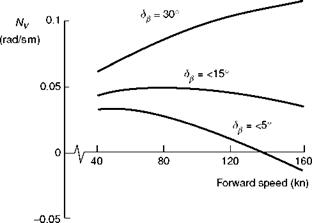
Fig. 4.28 Variation of weathercock stability derivative Nv with speed for different sideslip perturbations for Puma |
behaviour of the Dutch roll mode for the Puma can be attributed to the derivative Nv. In the previous discussion on this weathercock stability derivative, we observed that the Puma value was influenced by the strong nonlinearity in the force characteristics of the vertical fin with sideslip. At small angles of sideslip the fin sideforce is practically zero, due to the strong suction on the ‘undersurface’ of the thick aerofoil section (Refs 4.11,4.12). For larger angles of sideslip, the circulatory lift force builds up in the normal way. The value of the fin contribution to Nv therefore depends upon the amplitude of the perturbation used to generate the derivative (as with the yaw damping Nr, to a lesser extent). In Fig. 4.28, the variation of Nv with speed is shown for three different perturbation levels corresponding to <5°, 15° and 30° of sideslip. For the small amplitude case, the directional stability changes sign at about 140 knots and is the reason for the loss of Dutch roll stability illustrated in Fig. 4.25(b). For the large amplitude perturbations, the derivative increases with speed, indicating that the vertical fin is fully effective for this level of sideslip. Figure 4.29 presents the loci of Dutch roll eigenvalues for the three perturbation sizes as a function of speed, revealing the dramatic effect of the weathercock stability parameter. The mode remains stable for the case of the high sideslip perturbation level. It appears that the Puma is predicted to be unstable for small amplitudes and stable for large amplitude motion. These are classic conditions for so-called limit cycle oscillations, where we would expect the oscillation to limit in amplitude at some finite value with the mode initially dominated by roll and later, as the amplitude grows, to settle into a more conventional yaw/roll motion. We shall return to the nature of this motion when discussing response, in Chapter 5.