
Our heavyweight helicopter equal in the world does not have
In Rostov started production of the most load-lifting rotary-wing car The Russian holding «Helicopt[...]

Everything about aircrafts and helicopters. News and events in aviation worldwide. Civil, transportation, military helicopters and airplanes.

Everything about aircrafts and helicopters. News and events in aviation worldwide. Civil, transportation, military helicopters and airplanes.

Everything about aircrafts and helicopters. News and events in aviation worldwide. Civil, transportation, military helicopters and airplanes.

Everything about aircrafts and helicopters. News and events in aviation worldwide. Civil, transportation, military helicopters and airplanes.


This theory is based on the assumption that the aerofoil is thin so that its shape is effectively that of its camber line and the camber line shape deviates only slightly from the chord line. In other words, the
Figure 6.3
theory should be restricted to low angles of incidence. The modification to the aerofoil theory with the above simplifications are the following:
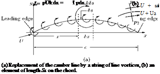
• Replacement of the camber line by a string of line vortices of infinitesimal strengths, as shown in Figure 6.3(a).
• The camber line is replaced by a line of variable vorticity so that the total circulation about the chord is the sum of the vortex elements. Thus, the circulation around the camber becomes:
Г = f kSs, (6.1)
J0
where k is the vorticity distribution over the element of camber line, Ss, circulation is taken positive (+ve) in the clockwise direction, as shown in Figure 6.3(a), and c is the chord of the profile.
Following Glauert, the leading edge is taken as the origin, ox along the chord and oy normal to it. The basic assumptions of the theory permit the variation of vorticity along the camber line be assumed to be the same as the variation along ox-axis, that is, Ss differs negligibly from Sx. Therefore, the circulation can be expressed as:
Г = I kdx. (6.2)
0
Hence the lift per unit span is given by:
L = pUr = pU I kdx. (6.3)
0
With pUk = p, Equation (6.3) can be written as:
![]()
 |
|
•c
Again for unit span, p has the units of force per unit area or pressure and the moment of these chordwise pressure forces about the leading edge or origin of the system is:
![]()
c
The negative sign for Me in Equation (6.5) is because it is conventional to take the nose-down moment as negative and nose-up moment as positive. For an aircraft in normal flight with lift acting in the upward direction, the moment about the leading edge of the wing will be nose-down. Thus, the thin wing section has been replaced by a line discontinuity in the flow in the form of a vorticity distribution. This gives rise to an overall circulation, as does the aerofoil, and produces a chordwise pressure variation. The static pressures p1 and p2 above and below the element Ss at a location with velocities (U + u{), (U + u2), respectively, over the upper and lower surfaces, are as shown in Figure 6.3(b). The overall pressure difference is (p2 — p1). By incompressible Bernoulli equation, we have:
1 , ,2 1 2
p1 + 2 P (U + U1) = p<x> + 2 pu
1 , ,2 1 2
p2 + 2P (U + u2) = p<x> + 2pU ’
where px is the freestream pressure. Therefore the overall pressure difference becomes:
For a thin aerofoil at small incidence, the perturbation velocity ratios u1/U and u2/U will be very small, and therefore, higher order terms can be neglected. Therefore, the overall pressure difference simplifies to:
The equivalent vorticity distribution indicates that the circulation due to the element Ss is kSx (Ss is replaced with Sx because the camber line deviates only slightly from the ox-axis).
Evaluating the circulation around Ss and taking clockwise circulation as positive in this case and by taking the algebraic sum of the flow of fluid along the top and bottom of Ss, we get:
![]() kSx = (U + U1)Sx — (U + u2)Sx = (u1 — U2)S.
kSx = (U + U1)Sx — (U + u2)Sx = (u1 — U2)S.
From Equations (6.6) and (6.7), it is seen that p = pUk, as introduced earlier.
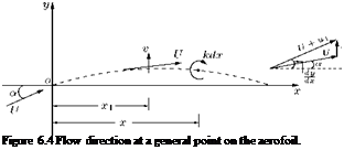 |
The flow direction everywhere on the aerofoil must be tangential to the surface and makes an angle tan-1 (dy/dx), since the aerofoil is thin, the angle dy/dx from ox-axis is as shown in Figure 6.4.
![]()
Resolving the vertical velocity components, we have:
since both dy/dx and a are small, tan dx approximated as ddx and sin a is approximated as a. Ignoring the second-order quantities, we can express the above equation as:
![]() (6.8)
(6.8)
The induced velocity v is found by considering the effect of the elementary circulation kSx at x, a distance (x — xj) from the point considered.
Circulation kSx induces a velocity at the point x1 equal to:
The effect of all such elements of circulation along the chord is the induced velocity v, where:
Using Equation (6.8) this becomes:
![]() (6.9)
(6.9)
The solution of kdx which satisfies Equation (6.9) for a given shape of camber line (defining dy/dx) and incidence can be introduced in Equation (6.4) and (6.5) to obtain the lift L and pitching moment M for the aerofoil shape. That is, using this circulation distribution (kdx), the lift and pitching moment can be calculated with Equations (6.4) and (6.5), respectively. From these L and Me, the lift coefficient CL and pitching moment coefficient CMu can be determined. Thus, once the circulation distribution is known, the characteristic lift coefficient CL and pitching moment coefficient CMu follow directly and hence the center of pressure coefficient, kcp and the angle of zero lift.


