Our heavyweight helicopter equal in the world does not have
In Rostov started production of the most load-lifting rotary-wing car The Russian holding «Helicopt[...]

Everything about aircrafts and helicopters. News and events in aviation worldwide. Civil, transportation, military helicopters and airplanes.

Everything about aircrafts and helicopters. News and events in aviation worldwide. Civil, transportation, military helicopters and airplanes.

Everything about aircrafts and helicopters. News and events in aviation worldwide. Civil, transportation, military helicopters and airplanes.

Everything about aircrafts and helicopters. News and events in aviation worldwide. Civil, transportation, military helicopters and airplanes.


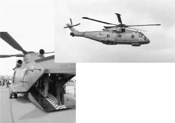
A special drag problem relates to the design of the rear fuselage upsweep for a helicopter with rear loading doors, where the width across the back of the fuselage needs to be more or less constant from bottom to top.
Figure 6.33 shows the difference in rear fuselage shape for a Merlin prototype in flight and a development (RAF) with a rear loading ramp door. In the 1960s, experience on fixed-wing
|
Figure 6.33 Shapes of Merlin fuselage both standard and that fitted with a rear loading ramp |
aircraft [13] revealed that where a rear fuselage was particularly bluff, drag was difficult to predict and could be considerably greater than would have been expected on a basis of classical bluff-body flow separation. Light was thrown on this problem in the 1970s by T. Morel [14,15]. Studying the drag of hatchback automobiles he found that the flow over a slanted base could take either of two forms: (1) the classical bluff-body flow consisting of cross-stream eddies or
(2) a flow characterized by streamwise vortices. Subsequently the problem was put into a helicopter context by Seddon [16], using wind tunnel model tests of which the results are summarized in Figures 6.34-6.37.
|
|
|
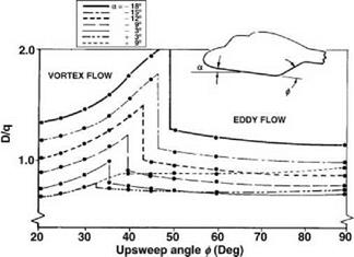
Figure 6.35 Variation of drag with upsweep angle at constant incidence |
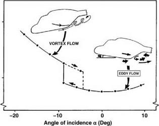
The combination of upsweep angle of the rear fuselage and incidence of the helicopter to the air stream determines the type of flow obtained. At positive incidence eddy flow persists. As incidence is decreased (nose going down as in forward flight) a critical angle is reached at which the flow changes suddenly to the vortex type and the drag jumps to a much higher level (Figure 6.34), which is maintained for further incidence decrease. If incidence is now increased, the reverse change takes place, though at a less negative incidence than before. The high drag corresponds to a high level of suction on the inclined surface, which is characteristic of the vortex flow. The suction force also has a downward lift component which is additionally detrimental to the helicopter. The type of flow is similar to that found on aerodynamically slender wings (as for example on the supersonic Concorde aircraft) but there the results are favourable because the lift component is upwards and the drag component is small except at high angle of attack.
|
|
|
Figure 6.37 Vortex flow development prevented by deflectors |
The effect of changing upsweep angle is shown in Figure 6.35. Here each curve is for a constant fuselage incidence. With upsweep angles near 90°, eddy flow exists as would be expected. At a point in the mid-angle range of upsweep, depending on incidence, the flow change occurs, accompanied by the drag increase. As the upsweep angle is further reduced the drag falls progressively but there is a significant range of angle over which the drag is higher than in eddy flow.
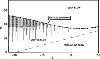
As an aid to design, the situation can be presented in the form of an a-f diagram, f being here the upsweep angle. The full line in Figure 6.36 is the locus of the drag jump when incidence is decreasing. If required, a locus can be drawn alongside to represent the situation with incidence increasing. Below the critical boundary is the zone of excess drag. From such a diagram, a designer can decide what range of upsweep angles is to be avoided for the aircraft. Of associated interest is the broken line shown: this marks an estimated boundary between vortex flow and streamlined flow, that is when no separation occurs at the upsweep. General considerations of aerodynamic streamlining suggest that the flow will remain attached if the upswept surface is inclined at not more than 20° to the direction of flight, in other words when f — a < 20°.
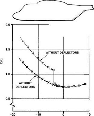
The final diagram, Figure 6.37, shows that if vortex flow occurs naturally, it can be prevented by an application of short, closely spaced deflectors on the fuselage side immediately ahead of the upswept face. The action is one of preventing the vortex from building up by cutting it off at multiple points along the edge.