
Our heavyweight helicopter equal in the world does not have
In Rostov started production of the most load-lifting rotary-wing car The Russian holding «Helicopt[...]

Everything about aircrafts and helicopters. News and events in aviation worldwide. Civil, transportation, military helicopters and airplanes.

Everything about aircrafts and helicopters. News and events in aviation worldwide. Civil, transportation, military helicopters and airplanes.

Everything about aircrafts and helicopters. News and events in aviation worldwide. Civil, transportation, military helicopters and airplanes.

Everything about aircrafts and helicopters. News and events in aviation worldwide. Civil, transportation, military helicopters and airplanes.


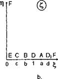
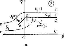
This local problem is of interest in connection with the possibility of increasing the reserve of efficiency of the power-augmented modes by providing shock-free entry of the tip of the leading edge. The scheme of the flow and the auxiliary plane are shown in Fig. 8.8, where x = (x — l)/h, у/hi, hi = h( 1), and Ъы is the length of the deflected part of the leading edge as a fraction of the leading edge ground clearance h. Here are the main steps and the results of the solution obtained by the method of singular points of S. A. Chaplygin. The complex conjugate velocity in the auxiliary plane can be derived in the form
d w + C + dx’W71′
dZ ^ CTb C-a 4 + 1 C-d)
![]()
|
|
|||
|
|||
|
|||
|
|||
|
|||
|
|||
|
|
||
|
|||
|
|||
|
|||
|
|||
|
|||
|
|||
|
|
||
|
|||
|
|||
|
|||
 |
|||
|
|||
|
|||

![]()
![]()
![]()
|
d£ — ^ief* |
|
t(t2 — c2) a + t t — 1 d + ts The magnitude of v* is determined by matching. For the remaining six unknowns, six equations are obtained, namely, (8.68), (8.71), (8.72), (8.73), (8.76), and (8.77). Accounting for the relationships |
|
v*0 + M v* — M ’ |
|
![]()
![]()
![]()
where
л/г b — c fl—cd–ceie/n
b = c/ ^l-v*/5h
we can reduce this system to one containing three unknowns a, c, and d and including equations (8.76), (8.77), and the additional condition
M – V* = 0. (8.78)
a — c
The suction force at point A can be determined by the formulas of S. A. Chaplygin
![]() die dw
die dw
dZd? dc’
 |
|||
Consideration of the last formula shows explicitly that it is possible to choose an angle of deflection of the leading edge tip that corresponds to shock-free entry, that is, zero suction force. This takes place at a = b. For a given length of the deflected part of the edge (forward flap) 6ief, this angle can be determined from the solution of the system
The normal force coefficient for the deflected part of the leading edge normalized with respect to bef is
![]()
![]() N fd (t-b)2 t-a (t-l d + te’°/* ,
N fd (t-b)2 t-a (t-l d + te’°/* ,
Ji t(t2 – c2) t + l ІГЙ cT^t)
and for zero suction force,
_ N_ fd t2~b2 (1~ 1 Af
П° Ъы Ji t(t2 — c2) t + ld — t)
 Без верификации!")