
Our heavyweight helicopter equal in the world does not have
In Rostov started production of the most load-lifting rotary-wing car The Russian holding «Helicopt[...]

Everything about aircrafts and helicopters. News and events in aviation worldwide. Civil, transportation, military helicopters and airplanes.

Everything about aircrafts and helicopters. News and events in aviation worldwide. Civil, transportation, military helicopters and airplanes.

Everything about aircrafts and helicopters. News and events in aviation worldwide. Civil, transportation, military helicopters and airplanes.

Everything about aircrafts and helicopters. News and events in aviation worldwide. Civil, transportation, military helicopters and airplanes.


To complete this chapter we turn from research topics to the practical problem of determining the aerodynamic design of a rotor for a new helicopter project as shown in Figure 6.39.
A step-by-step process enables the designer to take into account the many and varied factors that influence their choice – aircraft specification, limitations in hover and at high forward speed, engine characteristics at various ratings, vibratory loads, flyover noise and so on. The following exposition comes from an unpublished instructional document kindly supplied by Westland Helicopters.
The basic requirement is assumed to be for a helicopter of moderate size, payload and range, with good manoeuvrability, robustness and reliability. The maximum flight speed is to be at least 80 m/s and a good high-temperature altitude performance is required, stipulated as 1200 m at ISA + 28 K. Prior to determining the rotor configuration, a general study of payload and range diagrams, in relation to the intended roles, leads to a choice of all-up weight, namely 4100 kg. Empty weight is set at 55% of this value, leaving 45% disposable weight, of which it is assumed one-half can be devoted to fuel and crew. Consideration of various engine options follows and a choice is made of a pair of engines having a continuous power rating at sea level ISA of 560 kW each, with take-off and contingency ratings to match. Experience naturally plays a large part in the making of these choices, as indeed it does throughout the design process.
First choice for the rotor is the tip speed: this is influenced by the factors shown in Figure 6.40. The tip Mach number in hover is one possible limitation. Allowing a margin for the fact that in high-speed forward flight a blade at the front or rear of the disc will be close to the same Mach number as in hover but at a higher lift coefficient, corresponding to the greater power required, the hover tip speed limit is set at Mach 0.69 (235 m/s). On the advancing tip in forward flight the lift coefficient is low and the Mach number limit can be between 0.8 and 0.9; recognizing that an advanced blade section will be used, the limit is set at 0.88. Flyover noise is largely a function of advancing tip Mach number and may come into this consideration. High
 Aircraft Specification
Engine
Characteristics
Vibratory Loads
 High Speed Limitations
Figure 6.39 Typical helicopter design constraints
advance ratio brings on rotor vibratory loads and hence fuselage vibration, so a limiting m for normal maximum speed is set at 0.4. Lastly the maximum speed specified is at least 80 m/s. It is seen that the satisfaction of these requirements constrains the rotor tip speed to about 215 m/s, the targeted maximum flight speed being 160 knots (82 m/s).
Next to be decided is the blade area. The area required increases as design speed increases, because the retreating blade operates at decreasing relative speed while its lift coefficient is stall limited. The non-dimensional thrust coefficient CT/s is limited as shown in Figure 6.41a – see Equation 3.45. Writing:
![]() W pR 1 pA(OR)2 Nc
W pR 1 pA(OR)2 Nc
![]()
 |
W
I 2
pNcR(OR)2
we have for the total blade area NcR:
From a knowledge of tip speed (OR) and aircraft weight the blade area diagram, Figure 6.41b, is constructed. The design maximum speed then corresponds to a total blade area of 10 m2. Note that use of the advanced blade section results in about 10% saving in blade area, which translates directly into rotor overall weight.
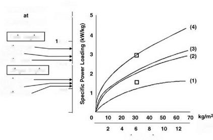
Choice of the rotor radius requires a study of engine performance. For the vertical axis in Figure 6.42, specific power loading (kW/kg) from the engine data is translated into actual power in W for the 4100 kg helicopter. Both twin-engine and single-engine values are shown, in each case for take-off, continuous and contingency ratings. Curves of power required for various hover conditions are plotted in terms of disc loading (kg/m2) on the established basis
(b)
 |
Determination of Blade Area
(Chapter 2) that induced power is proportional to the square root of disc loading. The four curves shown, reading from the lowest upwards, are:
(1) ideal induced power at sea level ISA, given by:
o being the disc loading;
 Disc Loading
Figure 6.42 Determination of rotor radius for new rotor design
(2) actual total power at sea-level ISA, scaled up from induced power to include blade profile power, tail rotor power, transmission loss, power to auxiliaries and an allowance for excess of thrust over weight caused by downwash on the fuselage;
(3) actual total power calculated for 1200 m altitude at ISA + 28°K;
(4) total power at sea level necessary to meet the requirement at (3), taking into account the decrease of engine power with increasing altitude and temperature.
A design point for disc loading can now be read off corresponding to the twin-engine take-off power rating (or using the contingency rating if preferred). From disc loading the blade radius follows, since:
![]() _ W _ W
_ W _ W
~ 1 ~ PR2
Hence:
![]()
(6.48)
In the present example the selected disc loading is 32 kg/m2 (314 N/m2) and the corresponding blade radius is 6.4 m. The single-engine capability has also to be considered. It is seen that on contingency rating the helicopter does not have quite enough power from a single engine to hover at sea-level ISA and full all-up weight. The deficit is small enough, however, to ensure that a good fly-away manoeuvre would be possible following an engine failure; while at 90% all-up weight, hovering at the single-engine contingency rating is just possible.
Undetermined so far is the number of blades. From a knowledge of the blade radius and total blade area, the blade aspect ratio is given by:
Using three blades, an aspect ratio of 12.3 could be considered low from a standpoint of three-dimensional effects at the tip. Five blades, giving aspect ratio 20.5, could pose problems in structural integrity and in complexity of the rotor hub and controls. Four blades are therefore the natural choice. Consideration of vibration characteristics is also important here. Vibration levels with three blades will tend to be high and with a reasonable flap-hinge offset, the pitch and roll vibratory moments (at NO frequency) will be greater for four blades than five. This illustrates that while a four-bladed rotor is probably the choice, not all features are optimum.
The choice between an articulated and a hingeless rotor is mainly a matter of dynamics and relates to flight handling criteria for the aircraft. A criterion often used is a time constant in pitch or roll when hovering; this is the time required to reach a certain percentage – 60% or over – of the final pitch or roll rate following an application of cyclic control. For the case in point, recalling the requirement for good manoeuvrability, low time constants are targeted. It is then found that, using flapping hinges with about 4% offset, the targets cannot be reached except by mounting the rotor on a very tall shaft, which is incompatible with the stated aims for robustness and compactness. A hingeless rotor produces greater hub moments, equivalent to flapping offsets of 10% and more, and is therefore seen as the natural choice.
References
1. Wilby, P. G. (1980) The aerodynamic characteristics of some new RAE blade sections and their potential influence on rotor performance. Vertica, 4,121-133.
2. Farren, W. S. (1935) Reaction on a wing whose angle of incidence is changing rapidly, R & M, 1648.
3. Carta, F. O. (1960) Experimental investigation of the unsteady aerodynamic characteristics ofNACA 0012 airfoil, United Aircraft Laboratory Report, M-1283-1.
4. Ham, N. D. (1968) Aerodynamic loading on a two-dimensional airfoil during dynamic stall. AIAA J., 6 (10), 1927-1934.
5. McCroskey, W. J. (1972) Dynamic stall of airfoils and helicopter rotors. AGARD Report 595.
6. Johnson, W. and Ham, N. D. (1972) On the mechanism of dynamic stall. JAHS, 17 (4), 36-45.
7. Beddoes, T. S. (1976) A synthesis of unsteady aerodynamic effects including stall hysteresis. Vertica, 1 (2), 113-123.
8. Wilby, P. G. and Philippe, J. J. (1982) An investigation of the aerodynamics of an RAE swept tip using a model rotor. Eighth European Rotorcraft Forum, Aix-en-Provence, Paper 25.
9. Byham, G. M. (1990) An overview of conventional tail rotors, in Helicopter Yaw Control Concepts, The Royal Aeronautical Society.
10. Keys, C. R. and Wiesner, R. (1975) Guidelines for reducing helicopter parasite drag. JAHS, 20,31-40.
11. Sheehy, T. W. (1975) A general review of helicopter hub drag data. Paper for Stratford AHS Chapter Meeting.
12. Seddon, J. (1979) An analysis of helicopter rotorhead drag based on new experiment. Fifth European Rotorcraft Forum, Amsterdam, Paper 19.
13. Lowe, B. G. and Trebble, W. J.G. (1968) Drag analysis on the Short SC5 Belfast, RAE Report.
14. Morel, T. (1976) The effect of base slant on the flow pattern and drag of 3-D bodies with blunt ends. General Motors Research Laboratories Symposium.
15. Morel, T. (1978) Aerodynamic drag of bluff body shapes characteristic of hatchback cars. SAE Congress and Exposition, Detroit, MI.
16. Seddon, J. (1982) Aerodynamics of the helicopter rear fuselage upsweep. Eighth European Rotorcraft Forum, Aix-en-Provence, Paper 2.12.
17. Stewart, W. (1952) Second harmonic control in the helicopter rotor, ARC R&M 2997, London.


