Our heavyweight helicopter equal in the world does not have
In Rostov started production of the most load-lifting rotary-wing car The Russian holding «Helicopt[...]

Everything about aircrafts and helicopters. News and events in aviation worldwide. Civil, transportation, military helicopters and airplanes.

Everything about aircrafts and helicopters. News and events in aviation worldwide. Civil, transportation, military helicopters and airplanes.

Everything about aircrafts and helicopters. News and events in aviation worldwide. Civil, transportation, military helicopters and airplanes.

Everything about aircrafts and helicopters. News and events in aviation worldwide. Civil, transportation, military helicopters and airplanes.


Case studies for new generation supersonic transport aircraft have been carried out through the past years in research institutions and in the aircraft industry. Our present tool to shape such configurations needs to be tested by trying to model the basic features of various investigated geometries. Knowing that the fine-tuning of aerodynamic performance must be done by careful selection of wing sections, wing twist distribution and the use of scaled slats and flaps, with initial exercises we try to geometrically model some of the published configurations, generate CFD grids around them and use optimization strategies to determine the sensitivity of suitable geometry parameters. This is still a difficult task but tackling its solution greatly contributes to building up the knowledge base of high speed design.
9.4.1 Example: Generic High Speed Civil Transport Configuration
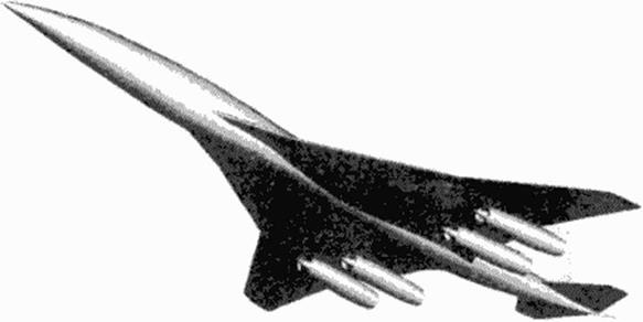
Figure 62 and Figure 63 illustrate data visualization of a generated configuration derived from a Boeing HSCT design case for Mach 2.4 (123J. The configuration consists of 10 components, engine pylons arc not yet included. Wing and horizontal and vertical tail components are spanwise defined, fuselage and engines are axially defined components. The wing has a subsonic leading edge in the inner portion and a supersonic leading edge on the outer portion.
|
|
|

^ГПТ-ЦЦ
Figure 63 Generic HSiT configuration: Three-view wireframe model
For this study a minimum of support airfoils (Figure 58) is used to get a reasonable pressure distribution: a rounded leading edge section in most of the inner wing and a wedge-sharp section in the outer wing portion define the basic shape of the wing. Wing root fillet blending, the smooth transition between rounded and sharp leading edge and the tip geometry are effectively shaped by the previously illustrated wing keys, the fuselage here is a simple slender body requiring just the baseline body tool with elliptical cross sections.
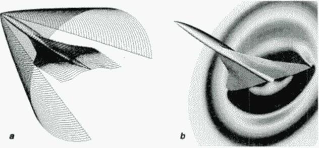
Preprocessing input data for CFD requires providing a gnd surrounding the configuration. For application of cither structured or unstructured grids additional geometric shapes need to be provided. In the case of the generic HSCT with given supersonic flight Mach number the farficld boundary is chosen to engulf the expected bow shock wave (Figure 64a) and a cross sectional grid for both wing and body is generated, cither as simple algebraic trajectories or using elliptic equations.
|
Figure 64 CFD grid boundaries, result for Euler analysis of HSCT wing-body in supersonic flow MM = 2.4 |
Short runs using an the inviscid flow Euler option of a flow solver [I24]wcrc carried out on a coarse (33 x 81 x 330) grid, here only to get an idea about the needed wing section and iwist modifications for acceptable pressure distributions. Visualization of the results in various gnd surfaces is needed, like pressure distributions in cross section planes as shown in Figure 64b.