
Our heavyweight helicopter equal in the world does not have
In Rostov started production of the most load-lifting rotary-wing car The Russian holding «Helicopt[...]

Everything about aircrafts and helicopters. News and events in aviation worldwide. Civil, transportation, military helicopters and airplanes.

Everything about aircrafts and helicopters. News and events in aviation worldwide. Civil, transportation, military helicopters and airplanes.

Everything about aircrafts and helicopters. News and events in aviation worldwide. Civil, transportation, military helicopters and airplanes.

Everything about aircrafts and helicopters. News and events in aviation worldwide. Civil, transportation, military helicopters and airplanes.


The usual way to connect two components is to intersect the surfaces Intersection curves arc found only by numerical iteration for non-invial examples. Most CAD systems perform such task if the data of different surfaces arc supplied. Here we stress an analytical method to find not only the juncture curve but also ensure a smooth surface across the components avoiding corners which usually create unfavorable aerodynamic phenomena. Sketched in Figure 61. this can be applied generally to two components Fj and Fs with the condition that for the first component one coordinate (here the spanwise y) needs to be defined by an explicit function у a F|(x. z), while the other component F may be given as a dataset for a number of surface points. Using a blending function for a portion of the spanwise coordinate, all surface points of Fj within this spanw ise interv al may be moved tow ard the surface F( depending on the local value of the blend-
 |
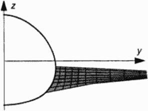 |
ing function. Figure 61 shows that this way the wing root (Fj) emanates from the body (F|), wing root Fillet geometry can be designed as part of the w ing prior to this wrapping process. Several refinements to this simple projection technique have been implemented to the program.


