Our heavyweight helicopter equal in the world does not have
In Rostov started production of the most load-lifting rotary-wing car The Russian holding «Helicopt[...]

Everything about aircrafts and helicopters. News and events in aviation worldwide. Civil, transportation, military helicopters and airplanes.

Everything about aircrafts and helicopters. News and events in aviation worldwide. Civil, transportation, military helicopters and airplanes.

Everything about aircrafts and helicopters. News and events in aviation worldwide. Civil, transportation, military helicopters and airplanes.

Everything about aircrafts and helicopters. News and events in aviation worldwide. Civil, transportation, military helicopters and airplanes.


To illustrate the principal effects of strong attitude control, we first examine pitch control and simplify the analysis by considering the longitudinal subset only. The essential features are preserved under this decoupled approximation. Strong control is assumed to be applied by the pilot or SCAS through simple proportional and rate feedback of pitch attitude to the longitudinal cyclic pitch
6s = кев + kqq, ke, kq < 0 (5.1)
where the gains к are measured in deg/deg (deg/deg s) or rad/rad (rad/rad s). Typical values used in limited authority SCAS systems are 0(0.1), whereas pilots can adopt gains an order of magnitude greater than this in tight tracking tasks. We make the assumption that, for high values of gain, the pitch attitude в and rate q, motions separate off from the flight path translational velocities u and w, leaving these latter variables to dominate the unconstrained modes. This line of argument leads to a partitioning of the longitudinal system matrix (subset of eqn 4.45) in the form
|
ГXu |
Xw |
Xq – We + kqXeu |
—g cos ®e + ke X e1s~ |
|
|
Zu |
Zw |
Zq — Ue + kqZeis |
—g sin ®e + k e Ze1s |
(5.2) |
|
——– |
||||
|
Mu |
Mw! |
Mq + kqMe1s |
k e Me1s |
|
|
0 |
0 : |
1 |
0 |
The derivatives have now been augmented by the control terms as shown. Before deriving the approximating polynomials for the low modulus (u, w) and high modulus (0, q) subsystems, we note that the transfer function of the attitude response to longitudinal cyclic can be written in the form
0(s) (Ug + ke)R(s) (5 3)
01s(s) = D(s) ( . )
where the polynomial D(s) is the characteristic equation for the longitudinal open-loop eigenvalues. The eigenvalues of the closed-loop system are given by the expression
![]() D(k) — (kkg + ke) R(k) = 0
D(k) — (kkg + ke) R(k) = 0
where the polynomial R(k) gives the closed-loop zeros, or the eigenvalues for infinite control gains, and can be written in the expanded form
R(k) = k2 — ^Xu + Zw — m— (MuX01s + MwZ01s)^J к
+ ( XuZw — ZuXw + —— (Xe1s (ZuMw — MuZw) + Ze1s (MuXw — MwXu)) )
M01s /
(5.5)
 |
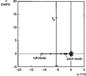
Equation 5.5 signifies that there are two finite zeros for strong attitude control and, referring to eqn 5.4, we can see a further zero at the origin for strong control of pitch rate. Figure 5.1 shows a sketch of the loci of longitudinal eigenvalues for variations in ke and kg. The forms of the loci are applicable to hingeless rotor configurations, which exhibit two damped aperiodic modes throughout the speed range. Articulated rotor helicopters, whose short-term dynamics are characterized by a short period oscillation, would exhibit a similar pattern of zeros. The two finite zeros shared by both the attitude and rate control loops are given by the roots of eqn 5.5 and both remain stable over the forward flight envelope. For strong control, we can derive approximations for the closed-loop poles of the augmented system matrix in eqn 5.2 from the weakly coupled
approximations to the low- (unconstrained motion) and high (constrained motion) order subsystems, as defined by the partitioning shown in eqn 5.2. The general form of the approximating quadratic is written as
k2 + 2^rnk + a>2 = 0 (5.6)
For the low-order subsystem, we can write
![]()
![]() 2z® = — (Xu + Zw ——— (MuXe1s + MwZe1s +—
2z® = — (Xu + Zw ——— (MuXe1s + MwZe1s +—
V M$1s V ke
*2 = (XuZw — ZuXw + Mbiifa — t)
X( ZuMw — MuZw ) + Ze1s (MuXw — MwXu)N)^)
and for the high-order subsystem
k2 — (Mq + kqMe1s) k — keMe1s = 0 (5.9)
The approximations work well for moderate to high levels of feedback gain (k 0(1)). For weak control (k O(0.1)) however, the approximations given above will not produce accurate results. To progress here we should have to derive an analytic extension to the approximations for the open-loop poles derived in Chapter 4. The terms in eqns 5.7 and 5.8 that are independent of the control derivatives reflect the crude, but effective, approximation found by perfectly constraining the pitch attitude. The two subsidences of the low-order approximation, which emerge from strong attitude control, are essentially a speed mode (dominated by u), with almost neutral stability, and a heave mode (dominated by w), with time to half amplitude given approximately by the heave damping Zw. The strongly controlled mode, with stability given by eqn 5.9, exhibits an increase in frequency proportional to the square root of attitude feedback gain, and in damping proportional to the rate feedback gain. The shift of the (open-loop) pitch and heave modes to (closed-loop) heave and speed modes at high gain is accompanied by a reduction in the stability of these flight trajectory motions, but the overall coupled aircraft/controller system remains stable.
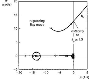
A concern with strong attitude control is actually not so much with the unconstrained motion, but rather with the behaviour of the constrained motion when the presence of higher order modes with eigenvalues further out into the complex plane is taken into account. The problem is best illustrated with reference to strong control of roll attitude and we restrict the discussion to the hover, although the principles again extend to forward flight. Figure 5.2 illustrates the varying stability characteristics of Helisim Lynx in hover with the simple proportional feedback loop defined by
etc = kфф, kф > 0 (5.10)
where, once again, the control may be effected by an automatic SCAS and/or by the pilot. The scale on Fig. 5.2 has been deliberately chosen for comparison with later results. The cluster of pole-zeros around the origin is of little interest in the present discussion; all these eigenvalues lie within a circle of radius < 1 rad/s and represent
|
Fig. 5.2 Root loci for varying roll attitude feedback gain for 6 DoF Lynx in hover |
the unconstrained, coupled lateral and longitudinal modes, none of which is threatened with instability by the effects of high gain. However, any system modes that lie in the path of the strongly controlled mode (shown as the locus increasing with frequency and offset by approximately Lp/2 from the imaginary axis) can have a significant effect on overall stability. Table 5.1 shows a comparison of the coupled system eigenvalues for the 6 DoF ‘rigid body dynamics’ and 9 DoF coupled dynamics cases, the latter including the flapping Dofs as multi-blade coordinates (see Chapter 3, eqns 3.55-3.63).
|
Table 5.1 Eigenvalues for 6 DoF and 9 DoF motions – Lynx in hover
|
Both first-order and second-order flapping dynamics have been included for comparison, illustrating that the regressing flap mode is reasonably well predicted by neglecting the acceleration effects in the multi-blade coordinates віс and ^is.
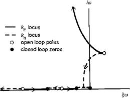
The similar modulus of the roll subsidence and regressing flap modes (both lie roughly on the complex plane circle with radius 10 rad/s), together with the presence of appreciable roll motion in the latter, signals that the use of the 6 DoF weakly coupled approximation for analysing the effects of strong roll control on the stability of lateral motion is unlikely to be valid. Observing the location of the regressing flap mode eigenvalue from Table 5.1, and referring to Fig. 5.2, we can also see that the regressing flap mode lies in the path of the root locus of the strongly controlled roll mode – another clear indication that the situation is bound to change with the addition of higher order flapping dynamics. The root loci of roll attitude feedback to lateral cyclic for the second-order 9 DoF model is shown in Fig. 5.3, revealing that the stability is, as anticipated, changed markedly by the addition of the regressing flap mode. The fuselage eigenvalues no longer coalesce and stiffen the roll axis response into a high – frequency oscillation, but instead the high-gain response energy becomes entrained in a coupled roll/flap mode which becomes unstable at relatively low values of gain, depending on the aircraft configuration. For the Lynx in hover illustrated in Fig. 5.3, the critical value of gain is just below unity. In practice, the response amplitude will be limited by nonlinearities in the actuation system for SCAS operation, or by the pilot reducing his gain and backing out of the control loop. Even for lower values of attitude gain, typical of those found in a SCAS (O(0.2)), the stability of the coupled mode will reduce to levels that could cause concern for flight through turbulence. To alleviate this problem, it is a fairly common practice to introduce notch filters into the SCAS that reduce the feedback signals and response around the frequency of the coupled fuselage/rotor modes. A similar problem arises through the coupling of the roll mode with the regressing lag mode when the roll rate feedback gain is increased, developing into a mode that typically has lower damping than the regressing flap mode;
|
|
|
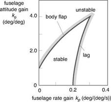
this problem has already been discussed in Chapter 3 (see Section 3.2.1 on lead-lag dynamics) where the work of Curtiss was highlighted (Ref. 5.5). Figure 5.4, taken from Ref. 5.5, shows Curtiss’s estimate of the stability boundary for rate and attitude feedback control. The example helicopter in Ref. 5.5 has an articulated rotor, but the level of attitude gain that drives the fuselage-flap mode unstable is very similar to Lynx, i. e., about 1°/° for zero rate gain. The level of stabilization through rate damping before the fuselage-lag mode is driven unstable is even lower, according to Curtiss, at 0.2°/° s.
High-gain attitude control is therefore seen to present a problem for pilots and SCAS designers. We can obtain some insight into the loss of damping in the roll/flap regressing mode through an approximate stability analysis of the coupled system at the point of instability. We make the assumption that the first-order representation of multi-blade flapping dynamics is adequate for predicting the behaviour of the regressing flap mode. We also neglect the low-modulus fuselage dynamics. From Chapter 3, the equations of motion for the coupled rotor-fuselage angular motion in hover are given by
The hub moment about the aircraft centre of mass is approximated by the expression
Me — ( N. Kp + ГкЛ (5.17)
which includes the moments due to thrust vector tilt and hub stiffness.
Equations 5.11-5.13 represent a fourth-order coupled system and when the attitude feedback law, given by eqn 5.10, is included, the order of the system increases to 5. For high values of feedback gain we make the assumption that the coupled roll regressing flap mode and the roll subsidence mode in Fig. 5.3 define the high-modulus system so that no further reduction is possible due to the similar modulus of the eigenvalues of these modes. This third-order system has a characteristic equation of the form
![]() A3 + ayU2 + $1^ + ao — 0
A3 + ayU2 + $1^ + ao — 0
The condition for stability of the coupled fuselage-flap mode can be written in the form of a determinant inequality (Ref. 5.6)
![]()
(5.19)
After rearrangement of terms and application of reasonably general further approximations, the condition for stability in terms of the roll attitude feedback gain can be written in the form
For the Lynx, the value of attitude gain at the stability boundary is estimated to be approximately 0.8°/° from eqn 5.20. The relatively high value of hub stiffness reduces the allowable level of feedback gain, but conversely, the relatively high rotorspeed on the Lynx serves to increase the usable range of feedback gain. On the Puma, with its slower turning, articulated rotor with higher Lock number, the allowable gain range increases to about 2°/°. Slow, stiff rotors would clearly be the most susceptible to the destabilizing effect of roll attitude to lateral cyclic feedback gain.
Later, in Chapter 6, we shall discuss some of the handling qualities considerations for attitude control. The potential for stability problems in high-gain tracking tasks will be seen to be closely related to the shape of the attitude frequency response at frequencies around the upper end of the range which pilots normally operate in closed-loop tasks. The presence of the rotor and other higher order dynamic elements introduces a lag between the pilot and the aircraft’s response to controls. The pilot introduces an even further delay through neuro-muscular effects and the combination of the two effects reduces the amplitude, and increases the slope of the phase, of the attitude response at high frequency, both of which can lead to a deterioration in the
pilot’s perception of aircraft handling. Further discussion on the influence of SCAS gains on rotor-fuselage stability can be found in Refs 5.7 and 5.8; Ref. 5.9 discusses the same problem through the influence of the pilot modelled as a simple dynamic system.
Now we turn to the second area of application of strong control and stability under constraint, where the pilot or automatic controller is attempting to constrain the flight path, to fly along virtual rails in the sky. We shall see that this is possible only at considerable expense to the stability of the unconstrained modes, dominated in this case by the aircraft attitudes.