Our heavyweight helicopter equal in the world does not have
In Rostov started production of the most load-lifting rotary-wing car The Russian holding «Helicopt[...]

Everything about aircrafts and helicopters. News and events in aviation worldwide. Civil, transportation, military helicopters and airplanes.

Everything about aircrafts and helicopters. News and events in aviation worldwide. Civil, transportation, military helicopters and airplanes.

Everything about aircrafts and helicopters. News and events in aviation worldwide. Civil, transportation, military helicopters and airplanes.

Everything about aircrafts and helicopters. News and events in aviation worldwide. Civil, transportation, military helicopters and airplanes.


Consider helicopter flight where the pilot is using the cyclic or collective to maintain constant vertical velocity w0 = w — Ue9. In the case of zero perturbation from trim, so that the pilot holds a constant flight path, we can write the constraint in the form
w = Ue9 (5.21)
When the aircraft pitches, the flight path therefore remains straight. We can imagine control so strong that the dynamics in the heave axis is described by the simple algebraic relation
Zuu + Zww ~ 0 (5.22)
and the dynamics of surge motion is described by the differential equation
du g
——– Xuu + — w = 0 (5.23)
dt Ue J
In this constrained flight, heave and surge velocity perturbations are related through the ratio of heave derivatives; thus
Zu
w ^———- – u (5.24)
Zw
and the single unconstrained degree of surge freedom is described by the first-order system
The condition for speed stability can therefore be written in the form
Xu + < 0 (5.26)
Ue Zw
For the Lynx, and most other helicopters, this condition is violated below about 60 knots as the changes in rotor thrust with forward speed perturbations become more and more influenced by the strong changes in rotor inflow. Hence, whether the pilot
![]()
applies cyclic or collective to maintain a constant flight path below approximately minimum power speed, there is a risk of the speed diverging unless controlled. In practice, the pilot would normally use both cyclic and collective to maintain speed and flight path angle at low speed. At higher forward speeds, while the speed mode is never well damped, it becomes stable and is dominated by the drag of the aircraft (derivative Xu). At steep descent angles the control problems become more acute, as the vertical response to both collective and cyclic reverses, i. e., the resulting change in flight path angle following an aft cyclic or up collective step is downward (Refs 5.10, 5.11).
Strong control of the aircraft flight path has an even more powerful influence on the pitch attitude modes of the aircraft, which also change character under vertical motion constraint. Consider the feedback control between vertical velocity and longitudinal cyclic pitch, given by the simple proportional control law
01s = kw0 w 0 (5.27)
Rearranging the longitudinal system matrix in eqn 4.138 to shift the heave (w0) variable to the lowest level (i. e., highest modulus) leads to the modified system matrix, with partitioning as shown, namely
|
Xu |
Xw – g cos &e/Ue |
Xq – We |
g cos &e/Ue |
|
Zu |
Zw |
Ue |
N 0 £ 1____ |
|
Mu |
Mw |
Mq |
kw0 M01s |
|
Zu |
Zw |
0 |
1 ф4 N о £ |
The damping in the low-modulus speed mode is approximated by the expression
and we note that as the feedback gain increases, the stability becomes asymptotic to the value given by the simpler approximation in eqn 5.26. If we make the reasonable assumptions
then the condition for stability is given by the expression
For the Lynx at 40 knots, a gain of 0.35°/(m/s) would be sufficient to destabilize the speed mode.
The approximation for the mid-modulus pitch ‘attitude’ mode is given by the expression
where we have used the additional approximations
Mels » UeMw (5.33)
Zeu * UeZw (5.34)
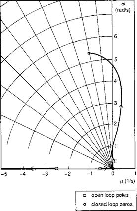
In the form of eqn 5.32, the approximation is therefore able to estimate only the location of the pitch mode at infinite gain. The mode is predicted to be stable, with a damping given by the pitch damping derivative and frequency by the pitch control sensitivity derivative. The mode has the appearance of a pendulum mode, with the fuselage rocking beneath the rotor, the latter remaining fixed relative to the flight path. An obvious question that arises from the above analysis relates to how influential this mode is likely to be on handling qualities and, hence, what the character of the mode is likely to be at lower values of gain. Figure 5.5 shows the root loci for the 3 DoF longitudinal modes of the Lynx at a 60 knots level flight condition. The locus near the origin is the eigenvalue of the speed mode already discussed, with the closed-loop zero at the origin (neutral stability). The root moving out to the left on the real axis corresponds to the strongly controlled vertical mode. The finite zero, characterizing the pitch mode,
|
|
is shown located where approximate theory predicts, with a damping ratio of about 0.2. Of particular interest is the locus of this root as the feedback gain is increased, showing how, for a substantial range of the locus (up to a gain of approximately unity), the mode is driven increasingly unstable. This characteristic is likely to inhibit strong control of the flight path in the vertical plane far more than the loss of stability in the speed mode.
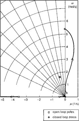
The moderately high frequency of the pitch mode at high values of gain suggests that there is the potential for coupling with the regressing flap mode. Figure 5.6 illustrates the same root loci for the 9 DoF Lynx model; the lower level oscillatory root on Fig. 5.6 represents the Dutch roll oscillation. The roll regressing mode is not shown on the axes range, but is actually hardly affected by the control. What does happen is that the pitch mode now becomes neutrally stable in the limit, with correspondingly more significant excursions into the unstable range at lower values of gain. Even when the open-loop pole has been stabilized through pitch attitude and rate feedback, we can expect the same general trend, with instability occurring at relatively low values of gain. The physical source of the instability is the reduction in incidence stability (Mw) resulting from the control of vertical velocity with cyclic pitch; a positive change
|
|
in incidence will indicate an increased rate of descent and will be counteracted by a positive (aft) cyclic, hence reducing static stability. A more natural piloting strategy is to use collective for flight path control and cyclic for speed and attitude control. At low to moderate speeds this strategy will always be preferred, and sufficient collective margin should be available to negate any pilot concerns not to over-torque the ro – tor/engine/transmission. At higher speeds however, when the power margins are much smaller, and the flight path response to cyclic is stronger, direct control of flight path with cyclic is more instinctive. The results shown in Figs 5.5 and 5.6 suggest a potential conflict between attitude control and flight path control in these conditions. If the pilot tightens up the flight path control (e. g., air-to-air refuelling or target tracking), then a PIO might develop. We have already seen evidence of PIOs from the analysis of strong attitude control in the last section. Both effects are ultimately caused by the loose coupling between rotor and fuselage and are inherently more significant with helicopters than with fixed-wing aircraft. PIOs represent a limit to safe flight for both types of aircraft and criteria are needed to ensure that designs are not PIO prone. This issue will be addressed further in Chapter 6.
The examples discussed above have highlighted a conflict between attitude control (or stability) and flight path control (or guidance) for the helicopter pilot. This conflict is most vividly demonstrated by an analysis of constrained flight in the horizontal plane (Ref. 5.12).