Our heavyweight helicopter equal in the world does not have
In Rostov started production of the most load-lifting rotary-wing car The Russian holding «Helicopt[...]

Everything about aircrafts and helicopters. News and events in aviation worldwide. Civil, transportation, military helicopters and airplanes.

Everything about aircrafts and helicopters. News and events in aviation worldwide. Civil, transportation, military helicopters and airplanes.

Everything about aircrafts and helicopters. News and events in aviation worldwide. Civil, transportation, military helicopters and airplanes.

Everything about aircrafts and helicopters. News and events in aviation worldwide. Civil, transportation, military helicopters and airplanes.


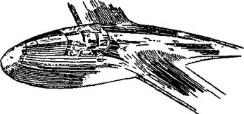
The flow over the fuselage is affected by the upwash and downwash caused by the wing. The approximate form of the streamlines is sketched in Fig. 11.2c and d. A way of reducing fuselage drag at one selected speed is to lay out the fuselage datum line as shown in Figure 11.2d, along the central streamline. Then the ordinates of a suitable low drag body are used, to construct a curved fuslage which follows the actual airflow. The result
|
|
will vary according to the presumed flow pattern. Without wind tunnel tests it is difficult to establish the correct form and even when done, it can apply only to one flight speed. Probably the gain is too slight to justify the effort.
In the early thirties, after considerable research, Alexander Lippisch designed the Fafnir 2 full-sized sailplane, which had a wing-fuselage junction resembling that of Figure 11.3. The fuselage was treated as if it were part of die wing, each longitudinal cross section being adjusted to produce lift, the idea being to carry the lift loading right across the span instead of allowing the fuselage to interfere. The result at one speed of flight was very good, but at other speeds it was less so. A somewhat similar, though less elaborately worked out, system was used on the ‘Fillon’s Champion’ model sailplane popular in the 1950s for free flight and radio control. It is probably better for all round performance to adopt the simplest low drag form, reduce cross sectional area as far as possible and add only the minimum fillets, for example, under the ‘armpits’ of a high wing sailplane, to fill in any sharp comers. Large fillets at the trailing edge may be necessary on some lowwinged aircraft, but in most cases the trailing edge should run straight to the fuselage, with a small fillet of the ‘radius’ type at the junction. Larger fillets here promote turbulence at all angles of attack except one. On sailplanes, refined fuselage design is aimed primarily at improving penetration at high speed. This should be borne in mind. A streamlined fuselage on an FI A (‘A2’) sailplane will possess only a very slight advantage since flight speeds are so low.
To reduce interference drag between wing and fuselage, or between any two components where they join, the first rule is that the angle of junction should not be less than 90 degrees. If two surfaces, or a stmt and another, larger component, join at a more acute angle, the air is forced to flow through a constricted channel and the drag increases rapidly as the angle becomes more acute. If such narrow channels cannot be avoided, they should be filleted; the fillet itself may be quite simple, but some care is needed to ensure that in itself it does not cause further flow separation problems (Fig. 11.4).