Our heavyweight helicopter equal in the world does not have
In Rostov started production of the most load-lifting rotary-wing car The Russian holding «Helicopt[...]

Everything about aircrafts and helicopters. News and events in aviation worldwide. Civil, transportation, military helicopters and airplanes.

Everything about aircrafts and helicopters. News and events in aviation worldwide. Civil, transportation, military helicopters and airplanes.

Everything about aircrafts and helicopters. News and events in aviation worldwide. Civil, transportation, military helicopters and airplanes.

Everything about aircrafts and helicopters. News and events in aviation worldwide. Civil, transportation, military helicopters and airplanes.


This chapter highlighted the rigid flapping-wing aerodynamics at the low Reynolds number range between O(102) and O(104). Similar to a conventional delta wing,
|
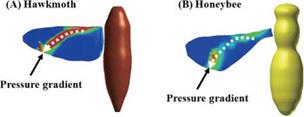
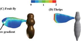
Normalized pressure gradient |
|
Figure 3.64. Spanwise pressure gradient contours on flapping wings around the middle of the downstroke: (A) a hawkmoth model (Re = 6.3 x 10³, k = 0.30); (B) a honeybee model (Re = 1.1 x 10³, k = 0.24); (C) a fruit fly model (Re = 1.3 x 10², k = 0.21), and (D) a thrips model (Re = 1.2 x 101, k = 0.25), respectively. |
a flapping wing can enhance lift because the vortex flow initiates at the leading edge of the wing, which rolls into a large vortex over the leeward side, containing a substantial axial velocity component. In both cases, vortex breakdown can occur, causing the destruction of the tight and coherent vortex. The LEV is a common feature associated with low Reynolds number flapping-wing aerodynamics; the flow structures are influenced by the swirl strength, the Reynolds number, and the rotational The effectiveness of LEVs in promoting lift is correlated with a flyer’s size. It seems that, at a fixed AoA, if the swirl is strengthened, then vortex breakdown occurs at lower Reynolds numbers. In contrast, a weaker swirling flow tends to break down at a higher Reynolds number. Hence, since the fruit fly, which operates at a lower Reynolds number range, exhibits a weaker LEV, it tends to better maintain the vortex structure than a hawkmoth and a honeybee, which create a stronger LEV. Furthermore TiVs associated with fixed finite wings are traditionally seen as phenomena that decrease lift and induce drag [297]. However, for flapping wings, the wing and vortex interactions, and consequently the aerodynamic outcome, can be far more complex. For a low-aspect-ratio hovering wing, with delayed rotation, TiVs can increase lift both by creating a low-pressure region near the wingtip and by anchoring the LEV to delay or even prevent it from shedding. Furthermore, for certain flapping kinematics such as synchronized rotation with modest AoA, the LEV remains attached along the spanwise direction and the tip effects are not prominent; in such situations, the aerodynamics is little affected by the AR of a wing. Appropriate combinations of advanced rotation and dynamic stall associated with large AoAs can produce more favorable lift. The combined effects of TiVs, LEV, and jet can be manipulated by the choice of kinematics to make a 3D wing aerodynamically better or worse than an infinitely long wing. Furthermore, the delayed stall of the LEV and interaction of TiVs and LEVs are significantly affected by the free – stream.
However, wing-wake interactions and TiVs can lead to a decrease in the aerodynamic performance when the wing orientation and the surrounding vortical flow structure are not well coordinated. Hence, the effectiveness of the unsteady flow mechanisms is strongly linked to the flapping wing kinematics, Reynolds number, and the free-stream environment.
This chapter also assessed the roles of Re, St, k, as well as kinematics at the Reynolds number of O(104), for both flat plate and SD7003 airfoil in forward flight with a shallow stall (pitch/plunge) and a deep stall motion (plunge). Massive leading – edge separation is observed at the sharp leading edge of the flat plate; its geometric effect is seen to dominate over other viscosity effects and the Re dependence is limited. For the blunter SD7003 airfoil, the flow is mostly attached for the shallow stall motion at Re = 6 x 10⁴, whereas it experiences massive separation for the deep stall motion. The deep stall kinematics produces a more aggressive time history of effective AoA with a higher maximum. The flow is characterized by a stronger leading-edge separation with earlier generation of an LEV and formation of a secondary vortex near the surface of the flat plate. The maximum lift coefficients of the flat plate are substantially different from those for the SD7003 airfoil. Furthermore, there is a noticeable phase lag in the deep stall SD7003 airfoil and flat plate in the time history of the lift coefficient. The difference in curvature of the leading-edge shape causes the lag in the generation and evolution of the LEV. Overall, for the shallow stall motion, the force acting on the SD7003 airfoil has smaller lift and drag compared to the force on the flat plate due to the formation of an LEV in the flat plate case. In contrast, the shape effects become less significant for the deep stall motion with higher maximum effective AoA: the flow separates over the SD7003 airfoil during the latter half of the downstroke, and the resulting force is similar to that of the flat plate.
The studies based on the kinematics and geometries of biological flyers offer direct evidence of unsteady aerodynamic mechanisms. Compared to flow structures generated by simple flapping motion, those around insect flapping wings have unique features, such as ring-like vortex generation per stroke with a strong downward jet.
We also highlighted selected linearized aerodynamic models used for control applications or design optimizations because their computational cost is significantly smaller than that of Navier-Stokes equation solutions; however, their applicability is not comprehensively understood in the flapping wing regime. Whereas quasi-steady models tend to over-predict the lift generation and may not able to capture wing – wake interactions with varied Reynolds numbers, they can still provide reasonable time-averaged lift estimations.
The chapter also presented several studies focusing on biological flyers, aimed at offering case studies in nature, as well as snapshots of interesting flow characteristics discussed in “canonical” investigations based on simplified problem definitions.
The topics discussed and highlighted in this chapter are essential to understand flapping wing aerodynamics with rigid wings. In Chapter 4 we discuss the effects of wing flexibility that increases the degree of freedom and showcase the challenges and intriguing features of multidisciplinary physics.