Particle image velocimetry (PIV)
Unlike the laser techniques described above, LDA and L2F, which provide velocity measurements at one point, PIV allows the examination of a whole section of the flow field and thus enables simultaneous measurement at different points, that is an essential requirement in unsteady motions. Usually two components of velocity are measured, but using a stereoscopic approach it is possible to obtain three components. The use of modern charged-couple device (CCD) cameras and dedicated computing
hardware permits velocity and vorticity maps in real time to be obtained, of the same type as those obtained in computational fluid dynamics (CFD) with the large eddy simulation technique.
4.5.1 PIV for studies of 2D fields
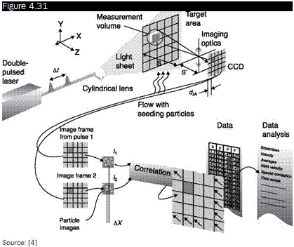
The test section is illuminated by a sheet of laser light produced by a cylindrical lens (Figure 4.31). This produces an image of the illuminated area on the matrix of pixels (typically 1k x 1k) of a CCD camera. To maximize the amount of light that reaches the camera, it should be placed in the direction of forward scatter, but the visual field would be reduced, the location chosen is usually normal to the direction of motion.
In the PIV, velocity vectors are determined by measuring the displacements of particles between two consecutive images of the stream:
Dt
 |
Diagram of a PIV apparatus for 2D fields
 |
To find the individual velocity vector, the images are divided into interrogation areas or sections or windows (Figure 4.32), in which it is assumed that all particles have the same speed. In order to obtain a significant measure, 10 to 25 particles must be contained in each area. The lateral size of the interrogation area, dIA, must be chosen, depending on the size of the structure of the stream that must be investigated. One way to express this is to state that the velocity gradient is negligible inside the interrogation area, for example, it must be:
V – V
^ minAt< 5%
dIA
The maximum measurable speed is limited by the particles that exceed the boundaries of the interrogation area in the time that elapses between the two laser pulses. The condition can be imposed:
The measurement volume can be defined once the size of the interrogation area and the thickness of the light sheet are known.
There are two possible procedures:
■ double-exposure image
■ two separate images.
The first procedure allows the movement of particles to be viewed and the structures present in the stream to be highlighted. To each area of interrogation a technique of autocorrelation is applied: denoting by
I(x, y) the intensity of light scattered by the particles, and by Z and h the shifts in the directions x and y, the convolution integral is applied in the interrogation area and the maximums are found:
R (£, n) = J J I(x, y) * I(x – £, y – n) dxdy
The absolute maximum identifies the null displacement, the overlapping of individual particles. The next maximum identifies the distance in the two directions between two consecutive positions of the particle. This procedure therefore does not determine the direction of the speed so it is not applicable in vortical zones where there are inversions of velocity.
To use the second procedure, it is necessary to use a CCD camera capable of capturing on separate frames the images produced by laser pulses. Once a couple of pulses are recorded, the areas of interrogation of both frames are cross-correlated pixel by pixel. In an interrogation window of M x N pixels (Figure 4.33), the common particle displacement can be calculated using the algorithm of cross-correlation:
M N
C(Ax Ay) =Y7LI1 (Ji j) * I2 ( – j – Dy)
,=i j=1
where Dx and Ay are possible displacements obviously limited by the condition that the particles do not exceed the boundaries of the window. The correlation produces a peak signal that identifies the common particle displacement Ax, Ay). Accurate measurement of displacement, and therefore of the speed, is obtained with a sub-pixel interpolation.
 |
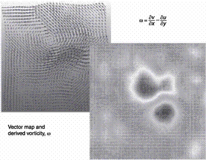
A map of the velocity vector in the whole investigated area is obtained by repeating the cross-correlation for each interrogation area on the two
 |
frames (Figure 4.34). In the same figure the corresponding map of vorticity is shown calculated from:
_dv-du Ю~ dx dy


