Our heavyweight helicopter equal in the world does not have
In Rostov started production of the most load-lifting rotary-wing car The Russian holding «Helicopt[...]

Everything about aircrafts and helicopters. News and events in aviation worldwide. Civil, transportation, military helicopters and airplanes.

Everything about aircrafts and helicopters. News and events in aviation worldwide. Civil, transportation, military helicopters and airplanes.

Everything about aircrafts and helicopters. News and events in aviation worldwide. Civil, transportation, military helicopters and airplanes.

Everything about aircrafts and helicopters. News and events in aviation worldwide. Civil, transportation, military helicopters and airplanes.


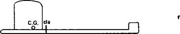
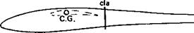
The cardboard cut-out method described in Fig. 12.13 for finding the neutral point for longitudinal stability resembles a method which is still sometimes advocated for determining the size of fin required on a model. This was originally suggested in its simplest form in Frank Zaic’s 1934 Yearbook. A side view of the model is drawn to scale on card, cut out and balanced to ensure that the so-called centre of lateral area falls behind the centre of gravity. If not, the fin area is adjusted until it does so. Unfortunately this method, although attractively simple, is based on a misunderstanding of the behaviour of fuselages. As mentioned above, a long slender body like a fuselage tends to turn broadside on to the airflow. Without a fin the fuselage of an aircraft will tend to turn the whole aircraft in this sense also. However long the fuselage, it will not naturally align itself with the direction of flight. As Fig. 12.14 shows, if the theory in this form is applied it indicates that no fin at all is required on most models, which is easily disproved by trying to do without one. This still occurs in most cases if the projected dihedral area is included in the cutout. Dihedral does have an important influence on lateral stability but if the fuselage is of normal length the simple method still suggests that the fin may be dispensed with in many cases, which is not so. From these results it is hard to believe that any successful model has ever really been designed by this 1934 method.
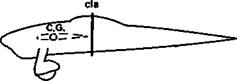
An elaboration of the c. I.a. theory was due to Charles H. Grant and described in his book, Model Airplane Design published in 1941.[3] The concern at that time was with free flight engine powered models for which high reserves of spiral stability were essential. The cardboard cutout is prepared as before but the dihedral and any other parts of the model which are duplicated on right and left sides (such as the undercarriage and wheels, or twin fins) are doubled in card thickness. The balancing procedure is then gone through and the c. I.a. located. This point should, according to Grant, lie on a horizontal line through the centre of gravity with the model in a level flying attitude, and about 30 to 35 % of the distance from the c. g. to the aerodynamic centre of the vertical tail surface. Further work was required to find the centre of lateral areas ahead of and behind the c. I.a. of the whole, and the line joining these was termed the displacement axis. A good deal was thought to depend on the precise relationship of this axis to the c. I.a. as a whole and to the centre of gravity.
If Grant’s methods are adopted, and some designers do still use them, successful models result. They turn out as a rule to be very similar in general layout and appearance to many other satisfactory models of similar general proportions, including canard designs and models with large floats for operation from water. Applied to aircraft of different proportions, especially to advanced modem sailplanes, aerobatic and pylon racing power models, the results turn out rather differently, especially if long, slender fuselages are used and if there is no wing dihedral.
It is probably fair to conclude that while the c. I.a. method produces safe models resembling many others already known to be satisfactory, it is nevertheless based on a shaky theoretical foundation and should not be relied on if anything much out of the ordinary is proposed.
The correct size of fin for a model can be computed by methods sometimes used in full – sized studies, but the work is lengthy and the results still not always reliable. Previous experience and trial are better guides, with a background of general theory to direct
|
|
|
|
|
|
|
|
|
|
|
|
|
|
|
|
|
![]()
experiments. The main principle is that fin and dihedral do need to be considered together. In practice, quite large variations in the size and disposition of the vertical tail areas are possible without greatly upsetting the control and handling of a radio controlled model.