Our heavyweight helicopter equal in the world does not have
In Rostov started production of the most load-lifting rotary-wing car The Russian holding «Helicopt[...]

Everything about aircrafts and helicopters. News and events in aviation worldwide. Civil, transportation, military helicopters and airplanes.

Everything about aircrafts and helicopters. News and events in aviation worldwide. Civil, transportation, military helicopters and airplanes.

Everything about aircrafts and helicopters. News and events in aviation worldwide. Civil, transportation, military helicopters and airplanes.

Everything about aircrafts and helicopters. News and events in aviation worldwide. Civil, transportation, military helicopters and airplanes.


Katz and Weihs [483] analyzed the generation of hydrodynamic forces by the motion of a uniform and massless flexible foil in a large-amplitude curved motion in an inviscid incompressible flow. They found that the chordwise flexibility increases the propulsive efficiency by up to 20 percent while causing small decreases in the overall thrust, compared with similar motion with rigid foils.
Pederzani and Haj-Hariri [484] performed computational analyses on a rigid wing from which a portion was cut out and covered with a very thin and flexible material (latex). They showed that due to a snapping motion (i. e., non-zero velocity in the direction opposite to that of the following stroke of the latex at the beginning of each stroke), the strength of the vortices that are shed is higher in lighter wing structures, leading to the generation of more thrust. Furthermore, snapping such structures requires less input power than snapping heavier ones. Using inviscid flow theory and beam equations, Chaithanya and Venkatraman [485] investigated the influence of inertial effects due to prescribed motion on the thrust coefficient and propulsive efficiency of a plunging/pitching thin plate. Their results demonstrated that flexible airfoils with inertial effects yield more thrust than those without inertial effects. This is due to the increase in the fluid loading in the former that subsequently leads to an increase in the deformation. Due to their shape, deformed airfoils produce a force component along the forward velocity direction [485].
Gopalakrishnan [486] analyzed the effects of elastic cambering of a rectangular membrane flapping wing on aerodynamics in forward flight using a linear elastic membrane solver coupled with an unsteady LES method. They investigated different membrane prestresses to give a desired camber in response to the aerodynamic loading. The results showed that the camber introduced by the wing flexibility increases the thrust and lift production considerably. Analysis of flow structures revealed that the LEV stays attached on the top surface of the wing, follows the camber, and covers a major part of the wing, which results in high force production. Attar et al.
[487] examined the effect of Strouhal number, reduced frequency, and static AoAs on the structural and fluid response of the plunging membrane airfoil. They showed that, at a low AoA and a low Strouhal number, increasing reduced frequency results in a decrease in the mean sectional lift and an increase in the drag coefficients; increasing the Strouhal number significantly affects the lift generation at a low AoA and an intermediate value of reduced frequency. They also observed that, when the effective AoA is studied for fixed values of the Strouhal number and reduced frequency, the act of plunging gives improved mean sectional lift when compared with the case of a fixed flexible airfoil (see Section 4.4.1). In contrast, for rigid wings, which they also considered, the LEV lifts off from the surface, resulting in low force production.
To evaluate the role played by the LEV for a flexibly cambered airfoil, Gulcat
[488] investigated (i) a thin rigid plate in a plunging motion, (ii) a flexibly cambered airfoil whose camber was changed periodically, and (iii) the plunging motion of a flexibly cambered airfoil. The leading-edge suction force for all cases was predicted by means of the Blasius theorem, and the time-dependent surface velocity distribution of the airfoil was determined by unsteady aerodynamic considerations. Gulcat [488] reported that the viscous effects obtained by the unsteady boundary-layer solution produce very little alteration to the oscillatory behavior of the net propulsive force. These forces only reduce the amplitude of the leading-edge suction force obtained by the unsteady aerodynamic theory. Heaving plunging makes the major contribution to the thrust; therefore, it is possible to get high propulsion efficiency with limited camber flexibility.
Miao and Ho [489] prescribed a time-dependent flexible deformation profile for an airfoil in pure plunge and investigated the effect of flexure amplitude on the unsteady aerodynamic characteristics for various combinations of Reynolds numbers and reduced frequency. For the specific combination of Reynolds number, reduced frequency, and plunge amplitude, the results showed that thrust-indicative wake structures are observed behind the trailing edge of those airfoils with flexure amplitudes of 0.0-0.5 of the chord length. This wake structure evolves into a drag- indicative form as the flexure amplitude of the airfoil is increased to 0.6 and 0.7 of the chord length. Studies conducted under various combinations of Reynolds numbers and reduced frequency showed that the propulsive efficiency of a chordwise flexible airfoil in pure plunge is influenced primarily by the value of the reduced frequency rather than by the Reynolds number.
Toomey and Eldredge [490] performed numerical and experimental investigations to understand the role of flexibility in flapping wing flight using two rigid elliptical sections connected by a hinge with a torsion spring. The section at the leading edge was prescribed with fruit-fly-like hovering wing kinematics [201], whereas the trailing-edge section responded passively due to the fluid dynamic and iner – tial/elastic forces. It was found that the lift force and wing deflection are primarily controlled by the nature of the wing rotation. Faster wing rotation, for example, leads to larger peak deflection and lift generation. Advanced rotation also leads to a shift in the instant of peak wing deflection, which increases the mean lift. In contrast to the rotational kinematics, the translational kinematics has very little impact on spring deflection or force. And although the rotational kinematics is nearly independent of the Reynolds number, the translational kinematics increases with increasing Reynolds number.
Poirel et al. [491] conducted a wind-tunnel experimental investigation of selfsustained oscillations of an aeroelastic NACA 0012 airfoil occurring in the transitional Re regime; in particular, aeroelastic limit cycle oscillations for the airfoil constrained to rotate in pure pitch. The structural stiffness and the position of the elastic axis were varied. Their investigation suggested that laminar separation plays a role in the oscillations, either in the form of trailing-edge separation or due to the presence of a laminar separation bubble.
Vanella et al. [492] conducted numerical investigations on a similar structure and found that the best performance (up to approximately 30 percent increase in lift) is realized when the wing is excited by a non-linear resonance at one third of its natural frequency. For all Reynolds numbers considered, the wake-capture mechanism is enhanced by a stronger flow around the wing at stroke reversal, resulting from a stronger vortex at the trailing edge.
Heathcote et al. [493] investigated the effect of chordwise flexibility on aerodynamic performance of an airfoil in pure plunge under hovering conditions. Because the trailing edge is a major source of shedding of vorticity at zero free-stream velocity, they showed that the amplitude and phase angle of the motion of the trailing edge affect the strength and spacing of the vortices, as well as the time-averaged velocity of the induced jet. Direct force measurements confirmed that, at high plunge frequencies, the thrust coefficient of the airfoil with intermediate stiffness is highest, although the least stiff airfoil could generate larger thrust at low frequencies. It was suggested that there is an optimum airfoil stiffness for a given plunge frequency and amplitude. Similar conclusions were made in another study [494] that analyzed the influence of resonance on the performance of a chordwise flexible airfoil prescribed with pure plunge motion at its leading edge. It was shown that although the mean thrust could increase with an increase in flexibility, below a certain threshold the wing is too flexible to communicate momentum to the flow. Yet, too much flexibility leads to a net drag, and hence, only a suitable amount of flexibility is desirable for thrust generation.
Although most of the recent computational and experimental studies have explored the role of wing flexibility in augmenting aerodynamic performance while focusing on single wings at relatively higher Reynolds numbers, Miller and Peskin [495] numerically investigated the effect of wing flexibility on the forces produced during clap-and-fling/peel motion [68] of a small insect (Re & 10) focusing on wingwing interactions. They prescribed both clap-and-fling kinematics separately to a rigid and a chordwise flexible wing and showed that, although lift coefficients produced during the rigid and flexible clap strokes are comparable, the peak lift forces are higher in the flexible cases than in the corresponding rigid cases. This is due to the peel motion that delays the formation of the TEVs, thereby maintaining vortical asymmetry and augmenting lift for longer periods [496].
Zhao et al. [497] investigated the chordwise flexibility effects on the LEVs and aerodynamic force generation using 16 different dynamically scaled mechanical flexible model wings in quiescent fluid at a Reynolds number of 2 x 10³ [498]. Findings from their experiments are that the magnitude of the LEV correlates with the aerodynamic forces generated by the flapping wing, and the camber influences instantaneous aerodynamic forces through the modulation of the LEV. Du and Sun [499] numerically investigated the effect of prescribed time-varying twist and chord – wise deformation on the aerodynamic force production of a fruit-fly-like model wing in hover. They showed that aerodynamic forces on the flapping wing are not affected much by the twist, but by the camber deformation. The effect of combined camber and twist deformation is similar to that of camber deformation alone. With a deformation of 6 percent camber and 20° twist (typical values observed for wings of many insects), the lift increases by 10-20 percent compared to the case of a rigid flat plate wing. They therefore showed that chordwise deformation could increase the maximum lift coefficient of a fruit fly model wing and reduce its power requirement for flight.
Lee et al. [500] numerically investigated a tadpole-type wing that consists of a rigid leading edge and a flexible plate at Re of 2.5 x 10³. They considered two elastic property distributions: homogeneous and linear. Their findings showed that the structural deformation changes the effective AoA, the vortex intensity, and the direction of the net force vector, resulting in a 13 percent increase in lift for the homogeneous type and a 33 percent increase in propulsive efficiency and force for the linear type distribution. Mountcastle and Daniel [501] numerically studied how aerodynamic force production and control potential are affected by pitch/elevation phase and variations in wing flexural stiffness. They showed that lift and thrust forces are highly sensitive to flexural stiffness distributions with performance optima that lie in different phase regions.
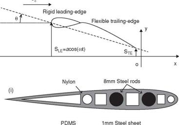
In another study, Heathcote and Gursul [336] performed water-tunnel studies to examine the thrust and efficiency of a flexible 2D airfoil plunging in forward flight. Their experimental setup is shown in Figure 4.28. Their airfoil was made up of a rigid teardrop 30 percent chord and a flexible flat plate 70 percent chord (see Fig. 4.28b). They changed the chordwise flexibility of the airfoil by changing the thickness of the flat plate. Following the experiment of Heathcote and Gursul [336], Kang et al. [351] explored the thrust enhancement induced by chordwise flexibility; they computed the thrust of a purely plunging chordwise flexible airfoil for different thickness ratios (h* = 4.23 x 10-3,1.41 x 10-3,1.13 x 10-3, 0.85 x 10⁻³, and 0.56 x 10⁻³) and motion frequencies that produce Strouhal numbers between St = 0.085 and 0.3 with 0.025 increments, with the plunge amplitude kept fixed to ha/cm = 0.194. The reduced frequency к then varies between 1.4 and 4.86. The airfoil consisted of a rigid teardrop leading edge and an elastic plate that plunged sinusoidally in the free-stream. As shown in Figure 4.29 variation in the thickness changes П1, whereas the motion frequency affects both к and St. Detailed experimental setup and discussion of fluid physics are in Heathcote and Gursul [336].
Shyy et al. [450] obtained a numerical solution for St = 0.17 for different thickness ratios. They used an Euler-Bernoulli beam solver to solve Eq. (4-1) for the
|
|
|
(b) |
|
(ii) |
V’ |
|
|
(iii) |
PDMS |
1mm Aluminium sheet |
 |
Figure 4.28. (a) Water-tunnel experimental setup for force measurements, wing deformation measurements, and PIV measurements; (b) chordwise flexible airfoil configuration; (c) cross-sections of spanwise flexible wing configuration. From Heathcote and Gursul [336] and Heathcote, Wang, and Gursul [502].
 |
deformation of the elastic flat plate, while the rigid teardrop moved with the imposed kinematics. Furthermore, the Reynolds number Re = 9.0 x 10³ and the density ratio p* = 7.8 were held constant in all cases. One of the mechanisms found by Shyy et al. [450] is that the chordwise deformation of the rear flexible plate in both flexible and very flexible cases results in an effective projected area for the thrust forces to develop. For St = 0.17, the thrust coefficient as a function of normalized time for the rigid, flexible, and very flexible wings is shown in Shyy et al. [450] and in Figure 4.29. To estimate the individual contribution of the teardrop and the flexible plate to force generation, the time histories of the thrust coefficient are shown separately for each element. The thrust response to variation in flexibility is different for each element: with increasing chordwise flexibility of the plate, the instantaneous thrust contributed by the flexible plate increases.
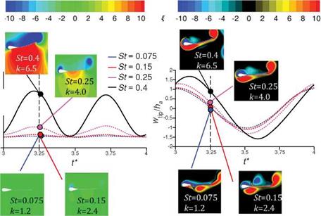
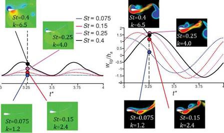
The interplay between the motion frequency indicated by St and the resulting thrust and wingtip displacement is further illustrated in Figure 4.30. For the flexible airfoil the resulting thrust generation increases with the increased motion frequency (к and St); the maximum wingtip displacement also shows monotonic increase with the motion frequency. A striking observation is that the vorticity field looks similar for all Strouhal numbers shown, but the pressure contours and the resulting thrust time histories differ in value. This could be related to the scaling proposed in Section
4.5 that the force acting on a moving body is largely dominated by the motion of the airfoil and less by the vorticity in the flow field at high reduced frequencies. A similar trend is shown for the very flexible airfoil, whose thickness ratio is about 2.5 times smaller than for the flexible airfoils. The thrust increases with higher к and St, but the maximum tip amplitude saturates for St = 0.15,0.25, and 0.4. Instead of resulting in a larger tip amplitude motion, higher motion frequency leads to a larger phase lag of the wingtip relative to the wing root. Increasing motion frequency leads to higher acceleration of the wing, and hence greater force generation. However, eventually the fluid dynamics time scale and reponse become limiting factors, as discussed in Section 4.5.
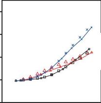
Figure 4.31 shows the time-averaged thrust coefficient for a range of motion frequencies from the numerical computation [351] and the experimental measurements [336]. For the thickest flat plate (h* = 4.23 x 10⁻³) the computed thrust compares well with the experimental measurements. At higher motion frequencies, St = 0.28 and
|
|
|
|
|
|
|
|
|
|
|
-2…………………………………………………….

![]()
![]()
 |
0 0.05 0.1 0.15 0.2 0.25 0.3 0.35
St
Figure 4.31. Time-averaged thrust coefficient for a plunging chordwise flexible airfoil at Re = 9.0 x 10³ and p* = 7.8 for different flat plate thickness and motion frequencies. The experimental data are extracted from Heathcote and Gursul [336]. From Kang et al. [351].
0.3, the computed thrust starts to deviate. A similar trend is observed for the other thicknesses: at h* = 0.85 x 10⁻³ the correlation between the numerical result and the experimental measurement is good until St = 0.23, and at h* = 0.56 x 10⁻³ it is good only at the lowest frequencies. Modeling uncertainties, such as laminar-to – turbulent transitions, non-linearities in the structural modeling, or non-negligible twist or spanwise bending in the experimental setup, which are not accounted for in the numerical computations, may be attributed to the observed differences. The thrust for the thickest airfoil (h* = 4.23 x 10⁻³) can be enhanced by increasing the motion frequency, which results in higher St and к. Increased St leads to greater fluid-dynamic force, and as shown in Section 3.6.4 increasing St and к further results in a greater acceleration-reaction force. Figure 4.31 also shows that the thrust generation depends on the thickness of the wing: At St = 0.125, [CT) for h* = 0.56 x 10⁻³ is the maximum, but for higher Strouhal numbers the thrust generated by the thinnest airfoil is the lowest. At St = 0.3, h* = 0.85 x 10⁻³ generates the highest thrust, while the thinnest wing, h* = 0.56 x 10⁻³ deteriorates in thrust.
To characterize the structural response, the tip displacement normalized to the plunge amplitude, wtip/ha, is plotted in Figure 4.32 as a function of the phase lag relative to the leading edge for the thicknesses and frequencies considered. The phase lag Ф is calculated by determining the time instant at which the trailing – edge displacement is a maximum. For the thickest airfoil, h* = 4.23 x 10⁻³, both the deformations and the phase lag are small. As we decrease the airfoil thickness, both wtip/ha and Ф increase with increasing frequency. Eventually, wtip/ha saturates when Ф approaches 90°: when Ф > 90° the motion of the deformed trailing edge is out of phase with the imposed leading edge. Relative to the leading-edge displacement, (wtip – Wroot)/ha shows that, by decreasing the stiffness and increasing the motion frequency, not only does the tip deformation increase monotonically but also the phase lag does, so that the resulting wingtip displacement reduces in magnitude
when the motion is out of phase (Fig. 4.31). The phase lag is known to be a critical parameter for flight efficiency [223] [454]. Due to the monotonic relation observed between (wtip – wroot)/ha and Ф, for the cases considered in this study, the role of the phase lag may be related to the relative maximum deformation, which is shown later to be the main parameter that describes the force and the propulsive efficiency scalings (Section 4.5.2). In Section 4.5 a relationship between the mean thrust and the structural response is established. Furtheremore, Spagnolie et al. [223] showed that when Ф < 180° the freely moving wing moves forward, and when Ф > 180° it moves backward. The phase differences observed in this study are smaller than 180°, producing thrust consistent with their observation. It is also remarkable to observe that the critical phase lag of 180° pointed out by Spagnolie et al. [223] corresponds to the maximum obtainable relative tip deformation, which occurs when the tip motion and the root motion are 180° apart.
In summary, considering the outcome from the studies conducted on chordwise flexible plunging/pitching structures discussed so far, three factors may play a vital role in aerodynamic force generation in hover/forward flight: (i) airfoil plunge motion modifies the effective AoA and aerodynamic forces; (ii) the relative motion of the leading edge and trailing edge creates the pitch angle that dictates the direction of the net force; and (iii) airfoil shape deformation modifies effective geometry such as camber.