Our heavyweight helicopter equal in the world does not have
In Rostov started production of the most load-lifting rotary-wing car The Russian holding «Helicopt[...]

Everything about aircrafts and helicopters. News and events in aviation worldwide. Civil, transportation, military helicopters and airplanes.

Everything about aircrafts and helicopters. News and events in aviation worldwide. Civil, transportation, military helicopters and airplanes.

Everything about aircrafts and helicopters. News and events in aviation worldwide. Civil, transportation, military helicopters and airplanes.

Everything about aircrafts and helicopters. News and events in aviation worldwide. Civil, transportation, military helicopters and airplanes.


The ability to generate rolling moments about the aircraft’s centre of gravity serves three purposes. First, to enable the pilot to trim out residual moments from the fuselage, empennage and tail rotor, e. g., in a pure hover, sideslipping flight, slope landings, hovering in side-winds. Second, so that the rotor thrust vector can be reoriented to manoeuvre in the lateral plane, e. g., repositioning sidestep, attitude regulation in tight flight path control. Third, so that the pilot can counteract the effects of atmospheric disturbances. All three can make different demands on the aircraft, and flying qualities criteria must try to embrace them in a complementary way.
6.3.1 Task margin and manoeuvre quickness
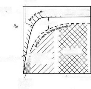
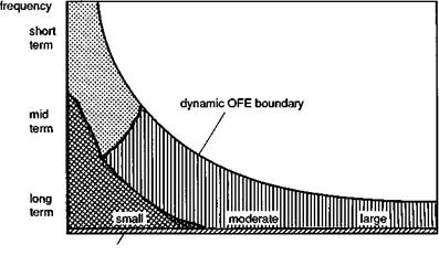
The roll axis has probably received more attention than any other over the years, possibly as a carry-over from the extensive research database in fixed-wing flying qualities, but also because roll control arguably exhibits the purest characteristics and is most amenable to analysis. A comprehensive review of roll flying qualities is contained in Ref. 6.15. In this work, Heffley and his co-authors introduced the concept of the ‘task signature’ or ‘task portrait’, discussed in Chapter 2 of this book (see Fig. 2.40), and also the ‘task margin’, or the control margin beyond that required for the task in hand. The basic ideas are summarized conceptually in Fig. 6.6, which shows how the roll rate requirements vary with manoeuvre amplitude (i. e., change in roll angle). The manoeuvre demand limit line is defined by the tasks required of the helicopter in the particular mission. The task margin is the additional vehicle capability required for emergency operations. The manoeuvre amplitude range can conveniently be divided into the three ranges discussed earlier – small, moderate and large – corresponding to precise tracking, discrete manoeuvring and maximum manoeuvre tasks, as shown.
 attitude change {йф)
Fig. 6.6 Roll rate requirements as a function of manoeuvre amplitude (Ref. 6.15)
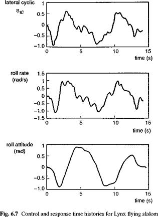
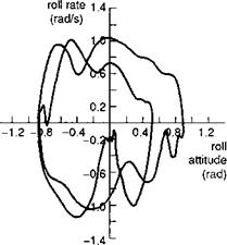
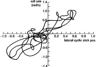
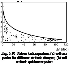
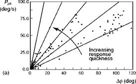
Highlighted in Fig. 6.6 are the principal design features that define the outer limit of vehicle capability – rotor stiffness in the small amplitude range and Lock number in the high amplitude range; the actuation rate and authority limits also define the shape of the capability boundary in the moderate to high amplitude range. To convert Fig. 6.6 into a form compatible with the frequency/amplitude diagram in Fig. 6.5 requires us to look back at the very simple task signature concept. Figure 6.7 shows the time histories of lateral cyclic, roll attitude and rate for a Lynx flying a slalom MTE (Ref. 6.16). The manoeuvre kinematics can be loosely interpreted as a sequence of attitude changes each associated with a particular roll rate peak, emphasized in the phase plane portraits in Fig. 6.8. For the case of the Lynx, roll control is essentially rate command, so that the attitude rate follows the control activity reasonably closely (see Fig. 6.9). The task signature portrait in Fig. 6.10 (a) shows selected rate peaks plotted against the corresponding attitude change during the slalom. Each point represents a discrete manoeuvre change accomplished with a certain level of aggression or attack. Points that lie on the same ‘spoke’ lines correspond to similar levels of attack by the pilot. We reserve the descriptors ‘attack’ and ‘aggression’ for the pilot behaviour, and use the expression ‘quickness’ to describe this temporal property of the manoeuvre. Manoeuvre quickness, or in the present case roll attitude quickness, is the ratio of peak rate to attitude change during a discrete manoeuvre and was first proposed in Ref. 6.15 as an alternate flying qualities or control effectiveness parameter:
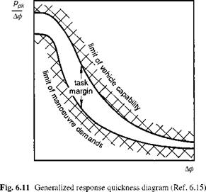
The data in Fig. 6.10 (a) are transformed into quickness values in Fig. 6.10 (b). If we transform the generalized boundaries on Fig. 6.6 into quickness, by plotting the slope
|
|
|
Fig. 6.8 Phase plane portrait for Lynx flying slalom manoeuvre |
![]()
|
|
 |
|
|
of the boundary lines against the attitude changes, we arrive at Fig. 6.11, showing the characteristic hyperbolic shape with amplitude of Fig. 6.5. For a given roll attitude change, there will be a maximum value of achievable quickness defined by the limit of the vehicle capability. When the manoeuvre amplitude is high enough, the limiting function in Fig. 6.11 will genuinely be hyperbolic, as the maximum rate is achieved and the limit is inversely proportional to the attitude change. This trend is confirmed in Fig. 6.10 (b), which shows the envelope of maximum quickness derived in the Lynx slalom flight trials described in Ref. 6.16. The highest roll attitude changes of more than 100° were experienced during the roll reversal phases of the MTE. Values of quickness up to 1 rad/s were measured during these reversals, indicating that pilots were using at least 100°/s of roll rate at the highest levels of aggression. In the low amplitude range the quickness rises to more than 5 rad/s, although with the small values of roll attitude change here, the extraction of accurate values of quickness is difficult. The quickness parameter has gained acceptance as one of the innovations of ADS-33, applicable to the moderate amplitude range of manoeuvres. We shall return to this discrimination later in this section but first we examine some of the theoretical aspects of quickness, applied to a simple model of roll control.
The first-order approximation to roll response has been discussed in Chapters 2,4 and 5, and the reader needs to be aware of the limited range of validity when applied to helicopters. Nevertheless, this simple model can be used to gain useful insight into the theoretical properties of quickness. We consider the first-order, differential equation of motion of a rate command response-type helicopter, written in the form
p Lpp — L 01c 01c — Lpps 01c (6.2)
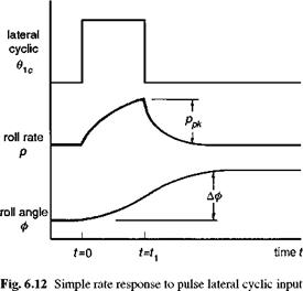
where p is the roll rate and 01 c the lateral cyclic control; we have neglected any rotor or actuation dynamics in this model. The damping and control derivatives have been discussed in detail in Chapter 4. The response to a step input in lateral cyclic is an exponential growth to a steady-state roll rate ps. To derive a value for attitude
quickness we need to consider the response to a pulse input of duration ti, which leads to a discrete attitude change Аф (Fig. 6.12). Analytic expressions for the roll rate and attitude response expressions then have two forms, one during the application of the pulse and the second after the pulse:
t < t1 : p = ps (1 – eLpt) 61c, ф = L – (1 + Lpt – eLpt) 91c
(6.3)
t > t1 : p = pseLpt (e-Lpt1 – 1) 91c, ф = ф(1 – L – (eLpt1 – 1)
(eLp(t-t1) – 1) 91c (6.4)
From these expressions the attitude quickness can be formed and, after some reduction, we obtain the simple expression
![]()
 |
M = – b-(1 – e-f1) Аф t1
where
t1 = —L pt1 (6.6)
The normalized time i) given by eqn 6.6 can be thought of as the ratio of the manoeuvre duration to the time constant of the aircraft. The quickness, normalized by the roll damping, is shown plotted against?1 in Fig. 6.13. One important result of this analysis is that the quickness is independent of control input size. For a 2-s pulse, the quickness will be the same from a small and large input; this is essentially a property of the linear system described by eqn 6.2 and may no longer be true when nonlinearities are
|
0.6 |
|
0.4 |
|
0.2 |
|
1.0 |
|
2.0 |
|
3.0 |
|
4.0 t: 5.0 normalized time |
Equation 6.8 tells us that when the manoeuvre is slow relative to the aircraft time constant, then the latter plays a small part in the quickness and the attitude change is practically equal to the roll rate times the pulse time. Equation 6.7 describes the limit for small-duration control inputs, when the roll transient response is still evolving. This case requires closer examination because of its deeper significance which should become apparent. The inverse of the roll damping is equal to the time to reach 63% of ps following a step input, but the parameter has another related interpretation in the frequency domain. Heuristically, frequency would appear to be more significant than amplitude in view of the insensitivity of quickness to control input size. The phase angle between the roll rate as output and the lateral cyclic as
(rjm amplitude

 When the phase between p and Qc is 45°, then the frequency is numerically equal to the damping Lp. This corresponds to the case when the attitude response is 135° out of phase with the control input. We shall see later in this section that the frequency when the attitude response lags the control by 135° is defined by a fundamental handling parameter – the (open-loop) attitude bandwidth. For non-classical response types we shall show that the attitude bandwidth is a more significant parameter than the roll damping and conforms more closely with many of the CACTUS rules. Bandwidth is one of the central parameters in ADS-33.
Returning to our framework diagram, we are now in a better position to examine quality criteria and the associated flight test measurement techniques; we divide the diagram into three ‘dynamic’ regions as shown (Fig. 6.14). We broadly follow the ADS-33 definition of the amplitude ranges:
(1) small, ф < 10°, continuous closed loop, compensatory tracking;
(2) moderate, 10° < ф < 60°, pursuit tracking, terrain avoidance, repositioning;
(3) large, ф > 60°, maximum manoeuvres;
and review selected military and civil criteria. On Fig. 6.14 we have included the narrow range of zero to very low frequency to classify trim and quasi-static behaviour. The first of the ‘manoeuvre’ regions combines moderate and large amplitude roll attitude criteria.