Our heavyweight helicopter equal in the world does not have
In Rostov started production of the most load-lifting rotary-wing car The Russian holding «Helicopt[...]

Everything about aircrafts and helicopters. News and events in aviation worldwide. Civil, transportation, military helicopters and airplanes.

Everything about aircrafts and helicopters. News and events in aviation worldwide. Civil, transportation, military helicopters and airplanes.

Everything about aircrafts and helicopters. News and events in aviation worldwide. Civil, transportation, military helicopters and airplanes.

Everything about aircrafts and helicopters. News and events in aviation worldwide. Civil, transportation, military helicopters and airplanes.


The economic efficiency of wing-in-ground-effect vehicles is directly related to the lift-to-drag ratio, which can be viewed as one of the principal design parameters. In what follows, some estimates of the lift-to-drag ratio of a lifting system in close proximity to the ground will be discussed on the basis of the simple Prandtl’s formula and the relevant results of the asymptotic theory set forth herein.
First of all, we write the induced drag coefficient of a lifting surface in the conventional form, introduced by Prandtl,
![]() = £L = £L,
= £L = £L,
7ГЛfl 7ГАЄ ’
where the function /і(/і, A) characterizes the influence of the ground and the wing aspect ratio upon the induced drag coefficient of a wing for a fixed magnitude of the lift coefficient. The quantity Ae = (i can be interpreted as an effective aspect ratio. As follows from the results of paragraph 3.4, the coefficient /і of a rectangular wing with a flat lower surface in the extreme ground effect can be calculated from the formula
|
A-*0, |
32 tanh^n tanh(gn/2)i2 /^tanh2<
qn — д (2n + 1). (9.30)
It follows from (9.29) and (9.30) that for h 0 and Cy = const., the magnitude of the induced drag coefficient diminishes proportionally to h as the wing approaches the ground. Hence, it is clear that for a lifting system operating near the ground, its effective aspect ratio depends, at least, upon one specific new parameter, the relative ground clearance.
From a practical viewpoint it is convenient to have at hand some simple formulas for evaluating the lift-to-drag ratio К == CyjCx as a function of Cy for the analysis of the existing margins for enhancing the maximum magnitude of Kmax or К for a given Cy.
Taking into account (9.29), we can write the expression for the aerodynamic fineness (lift-to-drag ratio) in the form
![]()
|
||
|
||
![]()
where CXQ is the viscous drag coefficient.
Similarly to the unbounded flow case, we can augment the lift-to-drag ratio of the lifting system by
• increasing the aspect ratio
• decreasing the induced drag by securing optimal spanwise distribution of the circulation by choosing an appropriate planform of the wing, as well as the distribution of the angle of attack (pitch) in the lateral direction;
• realizing the leading edge suction force; and
• reducing the viscous drag of the lifting system.
In addition, specific features of ground effect aerodynamics indicate that the magnitude of the lift-to-drag ratio can be increased by bringing the wing closer to the underlying surface (decreasing the relative ground clearance h) and/or mounting endplates at the tips of a wing.
The maximum of the function К takes place at a certain optimal magnitude of the lift coefficient
 (9.32)
and the corresponding magnitude of the maximum lift-to-drag ratio can be found by substituting (9.32) in (9.31):
|
|
|
|
|
|
Whereas the lift-to-drag ratio К specifies the aerodynamic efficiency of the lifting system, the product К U0 (where U0 is the design cruise speed) is closely related to its range of flight. Because the speed is inversely proportional to the square root of the lift coefficient, to find the maximum KU0, we can consider the following function:
y/Cy
СХ0+СЦ тгЛ/і*
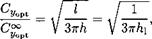
The maximum of this function takes place at a certain magnitude of the lift coefficient, which differs from (9.32), namely,
|
|
||
|
|||
|
|||
The magnitude of the lift-to-drag ratio, corresponding to the maximum range, is
1 ЗтгХц
We can draw some practical conclusions from the preceding results. First of all, the ratio of speeds, corresponding to the maximum lift-to-drag ratios for the ground proximity and an unbounded fluid is given by the expression
![]() &
&
which shows that, the more one gains in the lift-to-drag ratio by flying closer to the ground, the less the cruise speed of the vehicle. Second, going for a larger range entails a certain loss in the lift-to-drag ratio, compared to its maximum possible magnitude. This loss can be determined (in relative terms) by dividing expression (9.35) by expression (9.33):
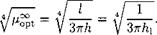
It is interesting to evaluate the reserves of enhancement of the maximum lift-to-drag ratio near the ground h —> 0 in comparison with the same property in unbounded flow, h -> oo. Suppose, that we compare optimal flat wings of the same relative span l. Keeping in mind that for an optimal wing operating out of the ground effect, h = oo, the loading distribution is elliptic, i. e.,
![]()
![]() (9.38)
(9.38)
we can derive from (9.14) the following expression for the coefficient /і = /i££t:
On the other hand, we can calculate the downwash w0, induced in the Tr – efftz plane by an optimal wing in unbounded fluid by using the following relationship:
Combining the two preceding expressions, we obtain the well-known Prandtl result: for an optimal wing in an unbounded fluid,
M~t = l, = (9.41)
The magnitudes of the maximum lift-to-drag ratio and the corresponding (optimal) lift coefficient for this case are
As shown in paragraph 9.2, for an optimal wing in the extreme ground effect (h —> 0), the distribution of the loading is parabolic. Therefore, the corresponding distribution of the circulation can be written as
![]() r(z) = rm(l-z2).
r(z) = rm(l-z2).
Substituting this formula in (9.4), we obtain the following expression for the factor /і = fiQpt when /і —> 0:
Now, we can derive a relationship between the downwash w0 and the parameter Гт, using formula (9.20) for the downwash behind the (straight) trailing edge of a wing in the extreme ground effect:
Finally, using the two preceding equations, we find that where h = h/l represents the distance from the trailing edge to the ground, related to the span of the wing.
Eventually, the capacity of the lifting surface without endplates to take advantage of the closeness to the ground can be evaluated with the help of the following formula:
Note that this formula was obtained by assuming that the loading is optimal both for h —> 0 and h —> oo.
The corresponding ratio of (optimal) lift coefficients in the extreme ground effect and an unbounded fluid has a similar form:
 (9.48)
Employing formulas (9.32) and (9.34), we can see that the cruise speed corresponding to the maximum range always exceeds that corresponding to the maximum lift-to-drag ratio. The ratio of these speeds is constant, and
![]()
Therefore, the expected gain in range, when flying in the extreme ground effect as compared to flying far from the ground (without accounting for the variation of the density of air) can be estimated by using the ratio

 (9.50)
To evaluate the margins connected with the realization of the suction force, it is beneficial to know the ratio of magnitudes of the maximum lift-to-drag ratio with fully realized suction force Km8iX to that with no suction force Kmax – We take example of a rectangular wing for h —» 0. If the flow near the leading edge is not separated, suction is realized, and the factor ц can be determined by equation (9.30). If there is no suction force, which may happen due to improper profiling of the leading edge, the factor fi for a wing of rectangular planform can be found in the form
 |
 |
Taking into account relationships (9.30) and (9.51), the loss in the lift-to-drag ratio when the suction force is not realized, can be assessed by the formula
For rectangular wings of small aspect ratios, it follows from expression (9.52) that
= y/2. (9.53)
-^•max
This is exactly the same result as that for unbounded flow. In Fig. 9.1, the calculated fraction Kmax/Kmax is plotted versus the aspect ratio A for h 1. In the same figure, the dashed line represents calculated data, corresponding to the motion of a rectangular wing in an unbounded fluid; see Belotserkovsky and Skripach [130].
We can deduce from the above analysis that for wings of moderate and large aspect ratios, realization of the suction force results in a larger increment of the maximum lift-to-drag ratio than in an unbounded fluid. Therefore, considerable attention should be paid to profiling the leading edge of the wing in the extreme ground effect.
5.0
![Подпись: 0 1 2 3 4 5 x б Fig. 9.1. The ratio of the maximum lift-to-drag ratio of a rectangular flat wing with suction force to that without suction force versus the aspect ratio (solid line: extreme ground effect; dashed line: out-of-ground effect [130]).](/img/3131/image1113.gif) Kmax
Kmax
77 4.5
‘Vnax
4.0
3.5
3.0
2.5
2.0
1.5
1.0
As already discussed, it is possible to improve the aerodynamic quality of lifting systems near the ground by mounting endplates on the tips of the wings. In this case, the efficiency factor /і should be replaced by /iep. Restricting consideration to the case of lower endplates, we can find the latter coefficient as
![]() /^ep(^? hep/h) — А)кер,
/^ep(^? hep/h) — А)кер,
where hep/h is the ratio of height of the endplate to the ground clearance and the factor кер = Cyep/Cy characterizes the relative augmentation of the lift coefficient due to the influence of the endplates and can be calculated by using (6.30). The maximum relative gain in the lift-to-drag ratio, resulting from the installation of lower endplates on a rectangular wing, can be evaluated by the formula[51]
![]()
![]() _______ ^ep_______
_______ ^ep_______
/l + (2 hep + в)/A where the denominator takes account of the augmentation of the wetted area of the wing due to mounting of the (lower) endplates and в is the adjusted pitch angle in radians.
Returning to Fig. 6.4, we can see that for a wing of a small aspect ratio in the presence of endplates, the gain in aerodynamic quality can be quite noticeable. For example, if the height of the lower endplates at the trailing edge constitutes 60% of the ground clearance, then, for a rectangular wing of
К
![]()
![]()

 aspect ratio Л = 0.7, flying at relative distance from the ground h = 0.07 at incidence в = 0.05, we can expect augmentation of the order of 25% of the maximum lift-to-drag ratio compared to that with no endplates.
For the optimal wing,[52] the maximum lift-to-drag ratio can be determined by the formula
= (9-56)
where /iopt is the optimal (maximal) magnitude of the coefficient (i.
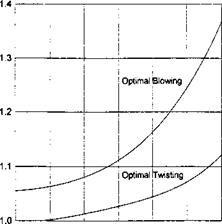
To decide whether it is worthwhile to attain an optimal spanwise loading distribution, it is practical to evaluate the following ratio:
Figure 9.2a presents the fraction (9.57) versus the aspect ratio Л for an optimal distribution of the angle of pitch for a rectangular wing in the extreme ground effect. Figure 9.2b shows the relative increment of the maximum lift – to-drag ratio for a wing with optimal organization of jet ejection along the trailing edge versus the aspect ratio in comparison with uniform blowing.
It is interesting to be able to evaluate the influence of the dynamic compressibility of air upon the lift-to-drag ratio. It was shown in section 5 that for
 |
a given Mach number, incompressible flow results can be used in compressible flow but for a smaller aspect ratio A’ = A^/l – M02, smaller clearance hf = hy/І" — M02, and larger angle of pitch в’ = ву/і – M02. Using the expression for the maximum lift-to-drag ratio given by (9.33) and assuming that the viscous contribution remains the same, we can roughly estimate the relative effect of compressibility on the maximum lift-to-drag ratio for different aspect ratios and Mach numbers; see Fig. 9.3.
We can use formula (9.31) to analyze the influence of different factors upon the lift-to-drag ratio of a flying wing of rectangular planform with end – plates on the basis of the one-dimensional nonlinear flow model developed in section 4. Following Rozhdestvensky [63] and Kubo [162], some results are represented herein of calculations illustrating the behavior of the lift-to – drag ratio of the previously mentioned simple configuration versus the design parameters. To evaluate the aerodynamic efficiency of a wing, a simplified calculation of the viscous contribution to drag is used, based on the concept of an equivalent flat plate, see Voitkunsky et al. [163] or Raymer [164]. Hence, it is assumed that a lifting system has viscous (friction) drag identical to that of a flat plate that has the same wetted area, length,[53] and speed. Correspondingly, the friction drag coefficient for fully developed turbulent flow is determined as
~ 0.455
f ~ (log Де)2 58’ (9-58)
where Re = UqCq/v is the Reynolds number based on the root chord and cruise speed. The area of the wetted surface of the flying wing configuration,
related to the square of the root chord Sw, is determined by the formula
Sw = 2A + SWep, (9.59)
where SWep is the wetted surface of (two) endplates of given configuration, related to the square of the chord length.
The latter quantity can be defined as
^ер = 4 /* hep(x)dx, (9.60)
Jo
where hep(x) is a given chordwise distribution of the height of the endplate as a fraction of the chord of the wing.
In the particular case of a flat wing and uniform distribution of the gap between the endplates and the ground, formula (9.60) yields the following result:
Sw = 2(A + 2/iep + 0), (9.61)
where hep represents the relative height of the endplate at the trailing edge.
Accounting for the fact that in the calculation of the lift and the induced drag coefficients, the reference area was that of the wing‘s planform, we can obtain the resulting expression for determination of the viscous drag coefficient[54] based on the wing reference area:
CX0 = Cf(2 + ^). (9.62)
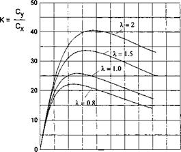
Figures 9.4-9.7 are graphs of the lift-to-drag ratio versus the lift coefficient. Figure 9.4 illustrates the influence of the relative ground clearance and the design lift coefficient upon the aerodynamic efficiency of a flat thin wing of rectangular planform with endplates. For each magnitude the design lift coefficient, the gap between the tips of the endplates and the ground is uniform chordwise.
It can be seen from the graph that, when a wing operates in the extreme ground effect, a decrease in ground clearance results in a considerable increase in the lift-to-drag ratio. At the same time, the optimal lift coefficient[55] increases. Figure 9.5 demonstrates the same tendencies for the influence of the gap under the endplates upon the aerodynamic efficiency of the configuration. The dashed lines correspond to the case when the leakage of the flow from under the endplates occurs with contraction; see the considerations on the effective gap in paragraph 4.3 and the solution of the local problem for contracted leaking flow under the endplate (or flap) in paragraph 8.1.3 of section 8.
 |
It is easy to conclude from Fig. 9.5 that a decrease in the gap under the endplates may result in considerable augmentation of the lift-to-drag ratio. Simultaneously, the optimum lift coefficient increases. In addition, realization
|
7 Fig. 9.6. The lift-to-drag ratio of a rectangular wing with endplates in the extreme ground effect versus the design lift coefficient for different aspect ratios (flat plate, gap uniform spanwise, h = 0.1, Re = 1.34 x 10⁹, Л = 1). |
of contraction of the flow escaping from underneath the vehicle may lead to significant gains in the aerodynamic efficiency.[56] The influence of the aspect ratio upon the lift-to drag ratio for a fixed gap under the tips of the endplates is shown in Fig. 9.6. This figure shows that the augmentation of the aspect ratio leads to an increase in the aerodynamic efficiency and increases optimun lift coefficient.
The dependence on the Reynolds number of both the lift-to-drag ratio and the magnitude of the optimum lift coefficient is illustrated in Fig. 9.7 and gives rise to an obvious conclusion: the larger the Reynolds number the larger the aerodynamic efficiency, and the smaller the optimum lift coefficient. The latter circumstance together with observations related to the influence of other design parameters, as discussed above, shows that the way to increase the cruise speed of the vehicle,[57] when flying close to the ground, consists of increasing the design Reynolds number. Other factors, leading to the enhancement of the lift-to-drag ratio, such as increase in the aspect ratio, decrease in the ground clearance and/or height of the endplates, result in a diminution of cruise speed for a given magnitude of wing loading.
Figure 9.8, plotted on the basis of the one-dimensional nonlinear theory of section 4, confirms the result discussed previously in this paragraph, namely, if suction force is not realized (e. g., due to stall) the efficiency may drop considerably.
 |
cy
Fig. 9.8. The lift-to-drag ratio of a rectangular wing with endplates in the extreme ground effect versus the design lift coefficient for realization of the suction force and no suction force (flat plate, gap uniform spanwise, h = 0.08, Re = 6 x 10⁸, A = 0.8, $ep/h = 0.25).