Our heavyweight helicopter equal in the world does not have
In Rostov started production of the most load-lifting rotary-wing car The Russian holding «Helicopt[...]

Everything about aircrafts and helicopters. News and events in aviation worldwide. Civil, transportation, military helicopters and airplanes.

Everything about aircrafts and helicopters. News and events in aviation worldwide. Civil, transportation, military helicopters and airplanes.

Everything about aircrafts and helicopters. News and events in aviation worldwide. Civil, transportation, military helicopters and airplanes.

Everything about aircrafts and helicopters. News and events in aviation worldwide. Civil, transportation, military helicopters and airplanes.


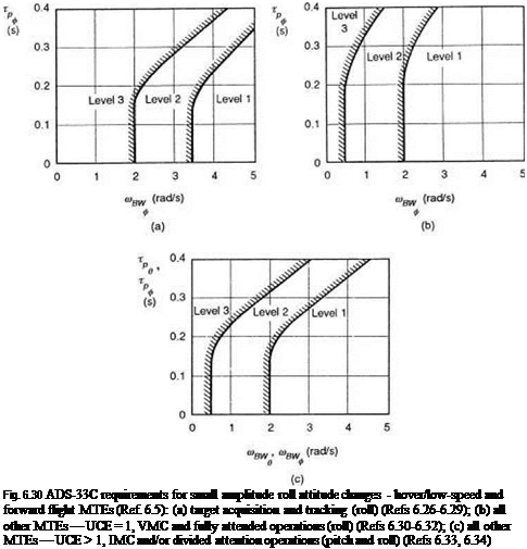
The ADS-33C quality boundaries for bandwidth and phase delay are presented on two – parameter handling qualities diagrams as shown in Figs 6.30(a)-(c), corresponding to the different MTE classes shown; the roll axis boundaries are applicable both to low speed and to forward flight regimes. The references provided in the legend to each figure record the supporting data from which the boundaries were developed. It is probably true that more effort has been applied, and continues to be applied, to defining these boundaries than any other. The criteria are novel and considerable effort was required to convince the manufacturing community in particular that the frequency domain criteria were more appropriate than the time domain parameters. The lower, vertical portions of each boundary indicate the minimum acceptable bandwidths, with tracking and air – combat MTEs demanding the highest at 3.5 rad/s for Level 1. The curved and upper portions of the boundaries indicate the general principle that the higher the bandwidth, the higher is the acceptable phase delay, the one compensating for the other.
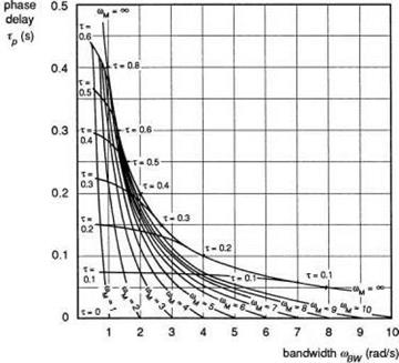
It may seem surprising that Level 1 handling qualities are possible with phase delays of more than 300 ms. Two points need to be made about this feature. First, a study of the references will indicate that, although the data in these areas is very sparse, they genuinely indicate the trends shown. Second, it would be practically impossible to build a helicopter with a bandwidth of, say, 3 rad/s and with a phase delay of 300 ms (Fig. 6.30(b)); the latter would almost certainly drive the bandwidth down to less than 1 rad/s. This dependence of bandwidth on the same parameters that have a first-order effect on phase delay is perhaps the only weakness of this two-parameter handling qualities diagram. The point is illustrated in Fig. 6.31, which shows the contours of equi-damping and time delay overlaid on the UCE 1 roll bandwidth boundaries. The contours are derived from a simple, rate response ‘conceptual handling qualities model’ (Refs 6.3, 6.35), which can be written in transfer function form
where K is the overall gain or, in this case, the rate sensitivity, т is a pure time delay; am can be considered to be equivalent to the roll damping, – Lp. The results in Fig. 6.31 show that the addition of a pure time delay can have a dramatic effect on both bandwidth and phase delay. With т set to zero, the bandwidth would be equal to rnm.
Therefore, a 70-ms pure time delay can reduce the bandwidth of a 12 rad/s aircraft (e. g., with hingeless rotor) down to 4 rad/s. The bandwidth reduction is much less significant on helicopters with low roll damping (e. g., with teetering rotors); the same lags reduce the bandwidth of a 3 rad/s aircraft to about 1.9 rad/s. Note that, according to Fig. 6.30(a), defining the roll bandwidth requirements for tracking tasks, a bandwidth of 4 rad/s corresponds to Level 1 while a bandwidth of 1.9 rad/s corresponds to Level 3.
The model similar to that described by eqn 6.12 was used to investigate the effects of different levels of pilot aggression, or task bandwidth, on the position of the handling qualities boundaries in Fig. 6.31, using the DRA advanced flight simulator (AFS) (Ref. 6.3). The results will be presented later in the discussion on subjective measurement of quality in Chapter 7, but the test results confirmed the ADS – 33C boundaries to within 0.5 HQR, up to moderate levels of aggression. The research reported in Ref. 6.3 was part of a larger European ACT programme aimed at
|
Fig. 6.31 Equi-damping and time delay contours overlaid on ADS-33C handling qualities chart (Ref. 6.8) |
establishing guidelines for the handling characteristics of future ACT helicopters (Ref. 6.36). This international programme made complementary use of ground-based and in-flight simulation facilities. Of particular concern was the effect of transport delays introduced by the digital computing associated with ACT, and tests were conducted to try to establish whether the curved boundaries on the ADS-33C criteria would still be appropriate. In a similar time frame a new series of flight and simulator tests was conducted under the US Army/German MoU to check the location of the upper phase delay boundaries (Ref. 6.37). A new lateral slalom task was derived that contained tight tracking elements that could potentially discern PIO tendencies. Both the EuroACT and US/GE research derived results that suggested a levelling of the phase delay boundary between 100 and 150 ms would be required. Figure 6.32 summarizes the results, showing the recommended phase delay caps from the two evaluations. At the time of writing, these recommendations are regarded as tentative, although they have led to a revision of the ‘official’ requirements, appearing in the latest version of ADS-33 (ADS – 33D, Ref. 6.38), as shown in Fig. 6.33. The reduction in phase delay is accompanied by a relaxation in the bandwidth requirement for roll tracking tasks. The evolution of these criteria illustrates once again the powerful effect of task on handling qualities and the strong design driver that handling qualities will be for future ACT helicopters.