Our heavyweight helicopter equal in the world does not have
In Rostov started production of the most load-lifting rotary-wing car The Russian holding «Helicopt[...]

Everything about aircrafts and helicopters. News and events in aviation worldwide. Civil, transportation, military helicopters and airplanes.

Everything about aircrafts and helicopters. News and events in aviation worldwide. Civil, transportation, military helicopters and airplanes.

Everything about aircrafts and helicopters. News and events in aviation worldwide. Civil, transportation, military helicopters and airplanes.

Everything about aircrafts and helicopters. News and events in aviation worldwide. Civil, transportation, military helicopters and airplanes.


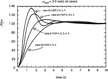
In Ref. 6.23, Hoh describes results from a simulator assessment of attitude command response types for a recovery to a ship MTE. The tests were conducted on the NASA vertical motion simulator (VMS) specifically to evaluate the effectiveness of rise time criteria. The step response characteristics of the different configurations tested are shown in Fig. 6.24. An important result of the tests was that the three evaluation pilots rated all the configurations within a fairly tight HQR spread. The pilots were
|
Fig. 6.24 Pilot HQRs for different step response characteristics at constant bandwidth (Ref. 6.23) |
almost unaware of the different time domain characteristics for this precision landing manoeuvre. What the configurations in Fig. 6.24 do have in common is the attitude bandwidth, even though the damping ratio varies from 0.5 to 1.3. This is a very compelling result and calls for a definition and description of this unique new handling qualities parameter.
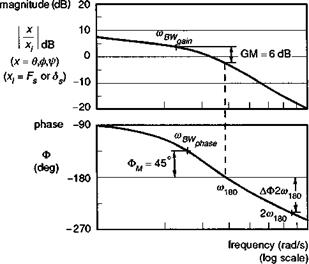
The bandwidth parameter is defined in Fig. 6.25 as the lesser of two frequencies, the phase-limited or gain-limited bandwidth, derived from the phase and gain of the
|
Fig. 6.25 Definition of bandwidth and phase delay from ADS-33 (Ref. 6.5) |
frequency response of attitude to pilot’s cyclic control. The phase bandwidth is given by the frequency at which the phase is 135°, i. e., the attitude lags behind the control by 135°. The gain bandwidth is given by the frequency at which the gain function has increased by 6 dB relative to the gain when the phase is 180°. The 180° phase reference is significant because it represents a potential stability boundary for closed- loop tracking control by the pilot. If a pilot is required to track a manoeuvring target or to maintain tight flight path control during turbulent conditions, then there are three related problems that hinder control effectiveness. First, at high enough frequencies, the aircraft response will lag behind the pilot’s control input by 180°, requiring the pilot to apply significant control lead to anticipate the tracked or disturbed motion (as the aircraft rolls to port, the pilot must also apply lateral cyclic to port to cancel the motion). Second, at higher frequencies the response becomes attenuated and, to achieve the same tracking performance, the pilot has to increase his control gain. Third, and most significant, any natural lags in the feedback loop between an attitude error developing and the pilot applying corrective cyclic control can result in the pilot-aircraft combination becoming weakly damped or even unstable. The combination of these three effects will make all air vehicles prone to PIOs above some disturbance frequency, and one of the aims of the bandwidth criteria is to ensure that this frequency is well outside the range required to fly the specified MTEs with the required precision. Thus, a high phase-bandwidth will ensure that the phase margin of 45°, relative to the 180° phase lag, is sufficient to allow the pilot to operate as a pure gain controller, accepting his own natural phase lags, without threatening stability. The gain bandwidth limit protects against instability should the pilot elect to increase his gain or his level of aggression at high frequency. Of course, a skilful pilot can operate effectively well beyond the limits defined by simple theory, by applying more complex control strategies. This always leads to an increase in workload and hence less spare capacity for the pilot to give attention to secondary tasks, any of which could become primary at any time in consideration of overall safety or survivability. For a wide range of systems, the phase bandwidth is equal to or less than the gain bandwidth.
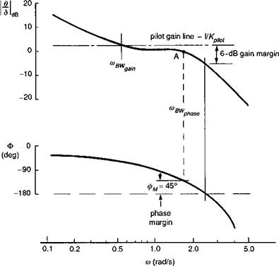
The bandwidth criteria apply in ADS-33 to both rate and attitude response-types, except that for attitude response types, only the phase bandwidth applies. This nuance leads us to examine the gain-limited bandwidth in a little more detail, following the discussion in Ref. 6.24, where Hoh reports that the ‘… gain bandwidth is included because a low value of gain margin tends to result in a configuration that is PIO prone. Low gain margin is a good predictor of PIO prone configurations because small changes in the pilot gain result in a rapid reduction in phase margin’. An example of a gain-limited bandwidth system is given in Ref. 6.24 and reproduced here as Fig. 6.26. Here, there is a modest value of phase bandwidth, but the gain margin available to the pilot when operating around this frequency, for example, to ‘tighten-up’ in an effort to improve performance, is limited and considerably less than the 6 dB available at the gain bandwidth. Hoh describes the problem succinctly when he states that, ‘The phenomenon is insidious because it depends on pilot technique. A smooth, nonaggressive pilot may never encounter the problem, whereas a more aggressive pilot could encounter a severe PIO’. Hoh goes on to discuss the rationale for not including the gain margin limit for attitude command systems. Basically, because the attitude stabilization task is accomplished by the augmentation system, the pilot should not be required to work at high gains with inner-loop attitude control. If he does, and experiences a PIO tendency, then simply backing off from the tight control strategy
|
Fig. 6.26 Example of a gain-margin limited system (Ref. 6.24) |
will solve the problem. To conclude this discussion we quote further from Hoh (Ref. 6.24):
We are faced with a dilemma: on the one hand gain-margin-limited ACAH response types lead to PIOfor super precision tasks, and on the other, disallowing such configurations robs the pilot ofworkload relieffor many other, less aggressive, MTEs. The approach taken herein (in the ADS-33C spec) has been to eliminate gain marginfrom the definition of bandwidth for ACAH response types, but to recommend avoidance of ACAH systems where the gain bandwidth is less than the phase bandwidth, especially if super precision tasks are required. Additional motivation for not including gain bandwidth as a formal requirement for ACAH was that the PIO due to gain margin limiting has not been found to be as violent for ACAH response types. It should be emphasised that this is not expected to be the case for rate or RCAH response types, where the pilot attitude closure is necessary to maintain the stable hover, and consequently, it is not possible to completely ‘back out’ of the loop. Therefore gain bandwidth is retained for these response types.
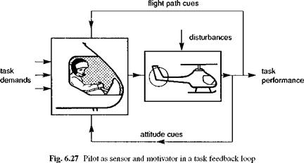
Gain-margin-limited systems result from a large phase delay, combined with flat amplitude characteristics such as shown in Fig. 6.27. Large phase delays usually result from inherent rotor system time delay (65 to 130 ms), combined with computer throughput delays, actuator lags, filters, etc. The flat amplitude characteristic is, of
|
course, inherent to ACAH, and can occur in RCAH response types due to the nature of feedforward equalization. |
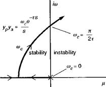
Another interpretation of bandwidth can be gleaned from its origins out of the development of the so-called crossover model of human pilot behaviour (Ref. 6.25), which treats the pilot action in performing tracking control tasks as an element in a feedback loop (Fig. 6.27). In single-axis tasks, for a wide variety of aircraft dynamic characteristics, the pilot adapts his control strategy so that the product of the pilot and aircraft dynamics take the simple transfer function form
coce-t s
Yp(s)Ya(s) « —————— (6.10)
s
Therefore, for example, if the rate response is a simple first-order lag, then the pilot will compensate by applying a simple lead with approximately the same time constant as the response lag. This form of overall open-loop characteristic will be applicable over a range of frequencies depending on the application. A key property of this form of model is highlighted by the root locus diagram of its stability characteristics when in a closed-loop system (Fig. 6.28). The pilot can increase the overall gain rnc to regulate the
|
Fig. 6.28 Root locus of crossover model eigenvalues as pilot gain is increased |
performance of the tracking task, but doing so will degrade the stability of the closed – loop system. The pure time delay, caused by mental processing and neuromuscular lags, is represented by the exponential function in the complex plane (i. e., Laplace transform) that has an infinite number of poles in the left-hand transfer function plane. The smallest of these moves to the right as the pilot gain is increased in the crossover model links up with the left moving rate-like pole, and the pair eventually become neutrally stable, with 180° phase shift, at the so-called crossover frequency as shown in Fig. 6.28. This simple but very effective model of human pilot behaviour has been shown to work well for small amplitude single-axis tracking tasks and leads to the concept of a natural stability margin defined by the gain or phase margin from the point of neutral stability. This is the origin of the bandwidth criteria.