Our heavyweight helicopter equal in the world does not have
In Rostov started production of the most load-lifting rotary-wing car The Russian holding «Helicopt[...]

Everything about aircrafts and helicopters. News and events in aviation worldwide. Civil, transportation, military helicopters and airplanes.

Everything about aircrafts and helicopters. News and events in aviation worldwide. Civil, transportation, military helicopters and airplanes.

Everything about aircrafts and helicopters. News and events in aviation worldwide. Civil, transportation, military helicopters and airplanes.

Everything about aircrafts and helicopters. News and events in aviation worldwide. Civil, transportation, military helicopters and airplanes.


The most appropriate parameter for defining the quality of flying large amplitude manoeuvres is the control power available, i. e., the maximum response achievable by applying full control from the trim condition. For rate command systems this will be measured in deg/s, while for attitude command response, the control power is measured in degrees. This ‘new’ definition found in ADS-33 contrasts with the earlier MIL-H – 8501 and fixed-wing criteria where the control power related to the maximum control
moment available. To avoid confusion we conform with the ADS-33 definition. Perhaps more than any other handling qualities parameter, the control power is strongly task dependent. Figure 6.15 illustrates this with the minimum control power requirements for Level 1 handling qualities (according to ADS-33) corresponding to MTEs that require limited, moderate and aggressive manoeuvring. The figure shows requirements for rate response types in low speed and forward flight MTEs. The minimum rate control power requirements vary from 15°/s in forward flight IMC through to 90°/s in air combat.
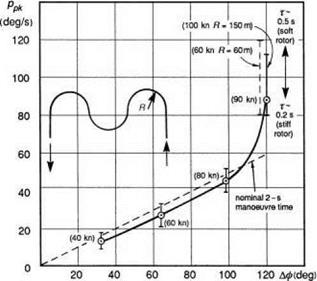
Ground-based simulations conducted at the RAE in the late 1970s (Ref. 6.17) were aimed at defining the agility requirements for battlefield helicopters and roll control power was given particular attention. Figure 6.16 shows the maximum roll rates used in the roll reversal phase of a triple bend manoeuvre as a function of roll angle change for various flight speeds. The dashed manoeuvre line corresponds to the theoretical case when the reversal is accomplished in just 2 s. For the cases shown, the control power was set at a high level (> 120°/s) to give the test pilots freedom to exploit as much as they needed. For speeds up to about 70 knots, the pilot control strategy followed the theoretical line, but as the speed increased to 90 and 100 knots there was a marked increase in the maximum roll rates used. This rapid change in control strategy at some critical point as task demands increase is significant and will be discussed later in Chapter 7. The spread of data points corresponds to different rotor configurations, resulting in different roll time constants as shown in the figure. With the larger time constants, corresponding to articulated or teetering rotor heads, the pilots typically used 30-40% more roll rate than with the shorter time constants typical of hingeless rotors. It appears that with ‘soft’ rotors, the pilot will use more control to quicken the manoeuvre. This more complex control strategy leads to an increase in
|
Fig. 6.16 Peak roll rates from triple bend manoeuvre |
workload and a degradation in the pilot opinion of handling qualities, a topic we shall return to in Chapter 7. The study of Ref. 6.17 concluded that for rapid nap-of-the-earth (NoE) manoeuvring in the mid-speed range, a minimum control power requirement of 100% was necessary for helicopters with moderately stiff rotors, typical of today’s hingeless rotor configurations.
The measurement of control power is, in theory, quite straightforward; establish trimmed flight and apply maximum control until the response reaches its steady state. In practice, unless great care is taken, this is likely to result in large excursions in roll, taking the aircraft to potentially unsafe conditions, especially for rate command response types. A safer technique is to establish a trimmed bank angle (< 60°) and apply a moderate step input in lateral cyclic, recovering before the aircraft has rolled to the same bank in the opposite direction. The manoeuvre can now be repeated with increasing control input sizes and several data points collected to establish the functional relationship between the roll response and control step size. Applying this incremental technique it will usually be unnecessary to test at the extremes of control input size. Either the minimum requirements will have been met at lower input sizes or the response will be clearly linear and extrapolation to full control is permissible. For the cases requiring the highest control powers, e. g., air combat MTEs, it may be necessary (safer) to capture the data in a closed-loop flight test, e. g., with the aircraft flown in an air combat MTE. In both open – and closed-loop testing, two additional considerations need to be taken into account. First, care should be taken to avoid the use of pedals to augment the roll rate. In operational situations, the pilot may choose to do this to increase performance, but it can obscure the measurement of roll control power. Second, at high rotor thrust, the rotor blades can stall during aggressive manoeuvring, with two effects. The loss of lift can reduce the roll control effectiveness and the increase in drag can cause torque increases that lead to increased power demands. These are real effects and if they inhibit the attainment of the minimum requirements then the design is lacking. Because of the potentially damaging nature of the test manoeuvres for control power estimation, online monitoring of critical rotor and airframe stresses is desirable, if not essential.
Neither the civil handling requirements (Ref. 6.10), nor Def Stan 00970 (Ref. 6.9), refer to criteria for control power per se, but instead set minimum limits on control margin in terms of aircraft response. This normally relates to the ability to manoeuvre from trimmed flight at the edge of the OFE. Def Stan 00970 defines control margin in terms of the control available to generate a response of 15°/s in 1.5 s. The old MIL-H-8501A required that at the flight envelope boundary, cyclic control margins were enough to produce at least 10% of the maximum attainable hover roll (or pitch) moment. The FAAs adopt a more flexible approach on the basis that some configurations have been tested where a 5% margin was sufficient and others where a 20% margin was inadequate (Ref. 6.13). Specifically, for FAA certification, what is required from flight tests is a demonstration that at the never-exceed airspeed, ‘a lateral control margin sufficient to allow at least 30° banked turns at reasonable roll rates’ must be demonstrated. ADS-33 is clearly more performance oriented when it comes to setting minimum control power requirements, and this philosophy extends to the moderate amplitude criteria, where the introduction of a new parameter, the manoeuvre quickness, has taken flying qualities well and truly into the nonlinear domain.
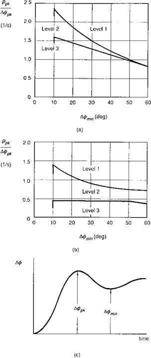
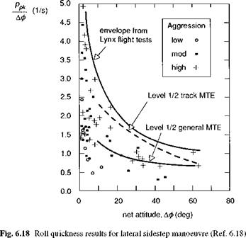
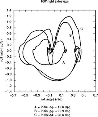
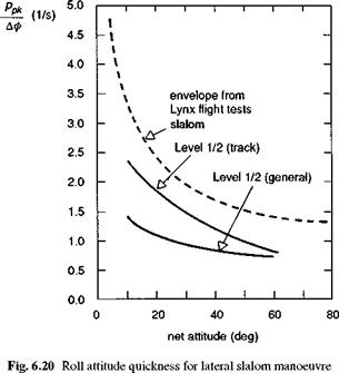
Moderate amplitude roll requirements broadly apply to manoeuvres within the range -60° <ф< 60° that include military NoEMTEs, such as quick-stop, slalom, and civil helicopter operations in harsh conditions, e. g., recovery to confined areas in gusty conditions and recovery following failed engine or SCAS. The development of attitude quickness has already been discussed in some detail. The definition of quickness used in ADS-33 has been developed to relate to non-pure response types and includes a subtlety to account for oscillatory responses. Figure 6.17 shows the roll axis quickness criteria boundaries from ADS-33, including the definition of the attitude parameters required to derive quickness. Once again the task-oriented nature of flying qualities is highlighted by the fact that there are different boundary lines for different MTE classes, even within the low-speed regime (see Ref. 6.5 for full details). Figure 6.18 shows the quickness envelope for the Lynx flying a lateral sidestep compared with the two Level 1 ADS-33 boundaries. The companion Fig. 6.19 illustrates the phase plane portraits for the sidestep flown at three levels of aggressiveness. Even in this relatively small-scale MTE, roll rates of nearly 70°/s are being used during the reversals (cf. Fig. 6.8). The sidestep task, flown in low wind conditions, strictly relates to the ‘general MTE’ class, indicating that the Lynx has at least a 60% task margin when flying this particular MTE. For the track boundary, the margin appears less, but it should be noted that the sidestep task in low wind is not the most demanding of MTEs and the Lynx will have a higher task margin than shown. To highlight this, Fig. 6.20 shows the roll quickness envelope for Lynx flying the lateral slalom MTE at 60 knots, with the ADS – 33 Level 1/2 boundaries for forward flight MTEs. The rise in quickness to limiting values occurred for this aircraft at the highest aspect ratio when the pilot reached the lateral cyclic stops in the roll reversals. Lynx is particularly agile in roll and we see in Fig. 6.20, possibly some of the highest values of quickness achievable with a modern helicopter. The additional points on Fig. 6.18 will be discussed below.
The compliance testing for quickness depends on roll response type; with rate command, a pulse-type input in lateral cyclic from the trim condition will produce a
![]()
|
|
|
|
Fig. 6.19 Phase plane portraits for Lynx flying lateral sidestep MTE |
|
|
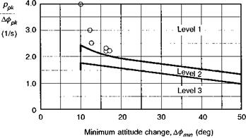
discrete attitude change. As noted above, for a helicopter with linear response characteristics, the quickness will be independent of input size and what is required is a decrease in the cyclic pulse duration until the required level of response is attained. In practice, the shorter the pulse, the larger the pulse amplitude has to be in order to achieve a measurable response. Figure 6.21 illustrates flight test results from the DLR’s Bo105, showing different values of roll quickness achieved between 10° and 20° attitude change (Ref. 6.19). A maximum quickness of 4 rad/s was measured for this aircraft at the lower limit of the moderate amplitude range. For longer duration inputs, quickness values only just above the ADS-33 boundary were measured, as shown, highlighting the importance of applying sharp enough inputs to establish the
|
Fig. 6.21 Roll attitude quickness measured on Bo105 at 80 knots (Ref. 6.19) |
quickness margins. It should be remembered that for compliance demonstration with ADS-33, all that is required is to achieve values in the Level 1 region.
For attitude response types, it may be necessary to overdrive initially the control input, followed by a return to steady state consistent with the commanded attitude. The control reversal is recommended to overcome the natural stability associated with the attitude command response type, and a moderate amount is allowable to achieve the maximum quickness.
The use of attitude quickness has some appeal in establishing control effectiveness requirements for civil helicopter handling qualities. As with the military requirements, however, establishing a test database from civil MTEs is essential before boundaries can be set. One area that could be well served by quickness is the response characteristics required to recover from SCAS failures; another could be the recovery from upsets due to vortex wakes of fixed-wing aircraft or other helicopters. Establishing quantitative criteria in these areas could have direct impact on the integrity requirements of the stability augmentation systems on the one hand and the operating procedures of helicopters at airports on the other. One of the obvious benefits of robust handling criteria is that they can help to quantify such aspects at the design stage.
In Fig. 6.18, the additional data points shown are computed from the time histories of sidestep data taken from tests conducted on the DRA advanced flight simulator (Ref. 6.3). These and other MTE tests will be discussed in more detail in Chapter 7, but a point worth highlighting here is the spread of quickness values in relation to the level of aggression adopted by the pilot. The level of aggression was defined by the initial roll angle, and hence translational acceleration, flown. High aggression corresponded to roll angles of about 30°, with hover thrust margins around 15%. At the lower end of the moderate amplitude range (between 10° and 20°), the maximum quickness achieved at low aggression was about 0.7, rad/s, which would correspond to the level of performance necessary to fly in UCE 2 or 3; ADS-33 states that meeting the quickness requirements is not mandatory for these cases (Ref. 6.5). The moderate aggression case would be typical of normal manoeuvring, and the maximum quickness achieved, around 1.5 rad/s, conforms well with the ADS-33 minimum requirement boundary. At the higher levels of aggression, quickness values correlate closely with those achieved with the Lynx in flight test at around 2.5 rad/s, a not-too-surprising result, as the simulation trials were designed to explore the maximum achievable task performance at similar thrust margins to the flight trials.
The large and moderate amplitude criteria extend down to 10° roll attitude. Below this, in the small amplitude range, we can see from Fig. 6.18 that the quickness measurements increase to values well beyond the moderate amplitude boundary. But quickness is no longer an appropriate parameter in this region and we have to look at a different formulation to measure flying quality here.