Our heavyweight helicopter equal in the world does not have
In Rostov started production of the most load-lifting rotary-wing car The Russian holding «Helicopt[...]

Everything about aircrafts and helicopters. News and events in aviation worldwide. Civil, transportation, military helicopters and airplanes.

Everything about aircrafts and helicopters. News and events in aviation worldwide. Civil, transportation, military helicopters and airplanes.

Everything about aircrafts and helicopters. News and events in aviation worldwide. Civil, transportation, military helicopters and airplanes.

Everything about aircrafts and helicopters. News and events in aviation worldwide. Civil, transportation, military helicopters and airplanes.


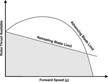
The envelope of rotor thrust limits is the combination of operation on the blades at the stall boundary both at high angle of incidence and with the compressibility effects at high Mach number. Usually the restrictions occur within the limits of available power. The nature of the envelope is sketched in Figure 7.6.
|
Figure 7.6 Nature of rotor thrust limits |
In hover, conditions are uniform around the azimuth and blade stall sets a limit to the thrust available. As forward speed increases, maximum thrust on the retreating blade falls because of the drop in dynamic pressure (despite some increase in maximum lift coefficient with decreasing resultant Mach number) and this limits the thrust achievable throughout the forward speed range. By the converse effect, maximum thrust possible on the advancing side increases but is unrealizable because of the retreating-blade restriction. However, at higher speeds, as the advancing-tip Mach number approaches 1.0, its lift becomes restricted by shock- induced flow separation, leading to drag rise or pitching moment divergence, which eventually limits the maximum speed achievable. Thus the envelope comprises a limit on thrust from retreating-blade stall and a limit on forward speed from advancing-blade Mach effects. Without the advancing-blade problem, the retreating-blade stall would itself eventually set a maximum to the forward speed, as the figure-of-eight diagrams in Figure 6.1 show.
Calculation of the limits envelope is best done by computer, allowing the inclusion of sophisticated factors, natural choices among which are a non-uniform induced-velocity distribution, a compressibility factor on lift slope (usually 1/8 where 8 = (1— M2)l=2, M being the blade section Mach number) and a representation of blade dynamic stall characteristics.
An example of the way in which the limits envelope can dominate performance issues is given later in Section 7.10.