
Our heavyweight helicopter equal in the world does not have
In Rostov started production of the most load-lifting rotary-wing car The Russian holding «Helicopt[...]

Everything about aircrafts and helicopters. News and events in aviation worldwide. Civil, transportation, military helicopters and airplanes.

Everything about aircrafts and helicopters. News and events in aviation worldwide. Civil, transportation, military helicopters and airplanes.

Everything about aircrafts and helicopters. News and events in aviation worldwide. Civil, transportation, military helicopters and airplanes.

Everything about aircrafts and helicopters. News and events in aviation worldwide. Civil, transportation, military helicopters and airplanes.


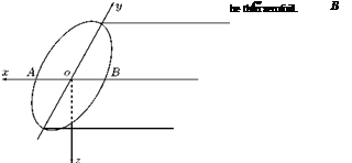
For thin aerofoils, which can be approximated by replacing them by their plan areas in the xy-plane, the acceleration potential can be applied comfortably. Let us consider such an aerofoil, shown in Figure 8.26(a), and replace it by its plan area represented by its section AB, shown in Figure 8.26(b).
If pu is the pressure at a point on the upper surface of AB and pi is the pressure at a corresponding point at the lower surface, then it can be shown that:
Pi — Pu = P (Фі — Фи) , (8.91)
where Фі and Фи are the corresponding values of the acceleration potential. Thus we have the lift and pitching moment as:
|
(Фі — Ф^ dS |
(8.92) |
|
S |
|
|
x (Фі — Фи) dS, |
(8.93) |
|
L = р |
|
M = р |
S
(b)
![]()
 |
where S is the surface area of the aerofoil planform. The center of pressure is at a distance xp = M/L from the origin.
The downwash velocity w is obtained by equating the values of the z-component of the acceleration, Equations (8.86) and (8.87). Thus:
dw дФ dx dz
But the downwash w vanishes at x = ж, therefore:
1 Г ЭФ
w = – —dx. (8.94)
V Л» dz
The induced drag is given by:
For a given y, the profile z = z(x, y) is determined by:
Example 8.5
A wing with elliptical loading, with span 15 m, planform area 45 m2 is in level flight at 750 km/h, at an altitude where density is 0.66 kg/m3. If the induced drag on the wing is 3222 N, (a) determine the lift coefficient, (b) the downwash velocity, and (c) the wing loading.
Solution
Given, 2b = 15 m, S = 45 m2, p = 0.66 kg/m3, V = 750/3.6 = 208.33 m/s.
W 180462.98
 ~S
~S
8.12 Summary
The vortex theory of a lifting aerofoil proposed by Lancaster and the subsequent development by Prandtl made use of for calculating the forces and moment about finite aerofoils. The vortex system around a finite aerofoil consists of the starting vortex, the trailing vortex system and the bound vortex system.
From Helmholtz’s second theorem, the strength of the circulation round any section of a bundle of vortex tubes is the sum of the strength of the vortex filaments cut by the section plane.
If the circulation curve can be described as some function of y, say f (y), then the strength of the circulation shed by the aerofoil becomes:
Sk = – f ‘(y) dy.
At a section of the aerofoil the lift per unit span is given by:
l = pUk.
The induced velocity at yi, in general, is in the downward direction and is called downwash.
The downwash has the following two important consequences which modify the flow about the aerofoil and alter its aerodynamic characteristics.
• The downwash at y1 is felt to a lesser extent ahead of y1 and to a greater extent behind, and has the effect of tilting the resultant wind at the aerofoil through an angle,
|
Zw |
w |
|
|
e = tan 1 |
Ы |
^~U |
The downwash reduces the effective incidence so that for the same lift as the equivalent infinite or two-dimensional aerofoil at incidence a, an incidence of a = a^ + e is required at that section of the aerofoil.
• In addition to this motion of the air stream, a finite aerofoil spins the air flow near the tips into what eventually becomes two trailing vortices of considerable core size. The generation of these vortices requires a quantity of kinetic energy. This constant expenditure of energy appears to the aerofoil as the trailing vortex drag.
The forward wind velocity generates lift and the downwash generates the vortex drag Dv.
This shows that there is no vortex drag if there is no trailing vorticity.
The expression k = f (y) which can be substituted in expression for L, w and Dv is:
The lift of an aerofoil of span 2b is:
The circulation for elliptical distribution is:
The downwash becomes:
This is an important result, which implies that the downwash is constant along the wing span. The drag caused by the downwash is:
Therefore, the drag coefficient becomes:
For modified elliptical loading:
The lift coefficient becomes:
The downwash for modified elliptic loading at any point y along the span is:
The vortex drag for modified loading is:
The drag coefficient becomes:
This drag coefficient for the modified loading is more than that for elliptical loading by an amount S, which is always positive since it contains X2 terms only.
If the lift for the aerofoils with elliptical and non-elliptical distribution is the same under given conditions, the rate of change of vertical momentum in the flow is the same for both. Thus, for elliptical distribution the lift becomes: ■b
![]() m wady.
m wady.
b
For non-elliptic distribution, the lift is:
L (X m (wo + Л(у))dy,
J-b
where m is a representative mass flow meeting unit span. But lift L is the same on each wing, therefore:
b
mfi(y) dy = 0.
b
Now the energy transfer or rate of change of the kinetic energy of the representative mass flow is the vortex drag (or induced drag). Thus, for elliptical distribution the vortex drag is:
1 / 2
Dva X 2 m J Wody.
For non-elliptic distribution the vortex drag is:
Lancaster-Prandtl lifting line theory is a representation to improve on the accuracy of the horseshoe vortex system. In lifting line theory, the bound vortex is assumed to lie on a straight line joining the wing tips (known as lifting line). Now the vorticity is allowed to vary along the line. The lifting line is generally taken to lie along the line joining the section quarter-chord points. The results obtained using this representation is generally good provided that the aspect ratio of the wing is moderate or large – generally not less than 4.
The integral equation from which the bound vorticity distribution may be determined is:
The lift generated by the wing is:
The lift coefficient is:
Thus, the lift coefficient Cl depends on A1, which in turn depends on the values and distribution of a and g.
The induced drag is:
where:
and is usually very small. Also, A1 = CL/n/R, so that:
where (1 + S) > 1, is the induced drag factor, and hence Г depends on the values of the Fourier coefficients, and hence on the wing geometry, especially on the planform.
For an aerofoil:
• Geometrical incidence is the angle between the chord of the profile and the direction of motion of the aerofoil.
• Absolute incidence is the angle between the axis of zero lift of the profile and the direction of motion of the aerofoil.
When the axes of zero lift of all the profiles of the aerofoil are parallel, each profile meets the freestream wind at the same absolute incidence, the incidence is the same at every point on the span of the aerofoil, and the aerofoil is said to be aerodynamically untwisted.
An aerofoil is said to have aerodynamic twist when the axes of zero lift of its individual profiles are not parallel. The incidence is then variable across the span of the aerofoil.
The drag and lift ratio can be expressed as:
|
Cdv ‘ |
w t |
|
Cl’ |
V ( |
For an actual aerofoil in a subsonic flow the main components of the drag are the profile drag and the skin friction drag. The induced drag caused by the downwash is an additional component of drag. Therefore, the total drag coefficient of the strip (profile), using Equation (8.24), is:
Cd’ = cd0 ‘ + (Cl ‘
where CDo’ is the coefficient of profile drag for the profile.
It may be noted that the profile drag is largely independent ofincidence in the working range. Profile drag is the sum of the skin friction due to viscosity and form drag due to the shape.
The form drag due to the shape is owing to the high pressure at the leading edge and low pressure at the trailing edge (that is the low pressure in the wake).
The following are the two problems associated with aerofoils:
• For a given circulation k(y), the form of the aerofoil and the induced drag are to be determined.
• For a given form of aerofoil, the distribution of circulation and the induced drag are to be determined.
In practice, in addition to induced drag there is profile drag due to skin friction and wake. The coefficient of profile drag is indicated by CD0. This the complete drag coefficient is:
Cd = Cd0 + Cdv.
The lift curve slope for an aerofoil of finite aspect ratio Ж with elliptical loading is:
If the aspect ratio is reduced to Ж and if the ‘primes’ refer to the new aerofoil with the same incidence, we have:
In problem I the aerofoil shape is found for a given circulation k(y). Problem II is an inverse problem in which, for a given aerofoil geometry the circulation is determined.
At the point of the trailing edge of an aerofoil, whose eccentric angle is в, we have:
For elliptic loading this becomes:
we = U Aj.
By Equation (8.7), we have:
We = —. 4b
Therefore:
which is constant across the wing span.
For wings with loading other than elliptic, the drag polar becomes:
where e is known as the Oswald wing efficiency and for elliptic loading e = 1.
For elliptic loading, S = 0 and e = 1, therefore, the drag polar becomes:
For drag minimum:
Rectangular aerofoil is an aerofoil whose planform is a rectangle. An aerofoil whose shape is that of a cylinder erected on an aerofoil profile satisfies this requirement.
Cylindrical rectangular aerofoil is the simplest type, of span 2b and chord c, which is constant at all sections. All the sections are similar and similarly situated.
In the general case, where the loading or lift distribution is not symmetrical about mid-span section, even terms appear in the distribution, and as a consequence of the asymmetry other characteristics of aerofoil appear.
When the lift distribution is not symmetrical about the centerline, one wing will have higher lift than the other and a net rolling moment about the longitudinal axis through the mid-span will result.
Further, as the lift is not symmetric nor is the spanwise distribution of circulation, the downwash will vary across the span without being symmetrical about the centerline and so will be the vortex drag grading. Hence, more drag will be experienced on one wing (the one with more lift) than on the other and a net yawing moment will result about the vertical (normal) axis through the mid-span section. In
addition to these there will be the overall lift and vortex drag force normal and parallel to the plane of the aerofoil in the plane of symmetry.
The lift acting on any section of spanwise length Sy at a distance y from the centerline (ox-axis) will produce a negative increment of rolling moment equal to:
ALr = —l y dy,
where l is the lift grading given by l = pVk. The total moment becomes:
![]() b r-b
b r-b
ly dy = — I pVk y dy.
b J—b
The asymmetrical drag grading across the span, gives rise to yawing moment N. The yawing moment can be expressed as:
|
where CN is the yawing moment coefficient.
Lifting surface theory is a method which treats the aerofoil as a vortex sheet over which vorticity is spread at a given rate. In other words, the aerofoil is regarded as a surface composed of lifting elements. This is different from the lifting line theory. The essential difference between the lifting surface theory and lifting line theory is that in the former the aerofoil is treated as a vortex sheet, whereas in the latter, the aerofoil is represented by a straight line joining the wing tips, over which the vorticity is distributed.
Munk’s theorem of stagger states that “the total drag of a multiplane system does not change when the elements are translated parallel to the direction of the wind, provided that the circulations are left unchanged.” Thus the total induced drag depends only on the frontal aspect.
The total drag mutually induced on the pair of lifting elements becomes:
, j2n pTxTzdsxdsz cos^! + ф2)
d Di2 + d D21 = —————— ~———————– 2——— ,
2n n2
which is independent of the angle of stagger. This yields Munk’s theorem of stagger, that is:
“the total drag of a multiplane system does not change when the elements are translated parallel to the direction of the wind, provided that the circulations are left unchanged."
When the system is unstaggered (that is, when в = 0):
d2Di2 = d2D21
and thus if the lifting systems are in the same plane normal to the wind, the drag induced in the first by the second is equal to the drag induced in the second by the first. This result constitutes Munk’s reciprocal theorem.
The total mutual induced drag is:
p Гi Г2 cos (фі + ф2) 2n n2
Blenk’s method is meant for wings of finite aspect ratio and is based on the lifting line theory of Prandtl, hence limited to aerofoils moving in the plane of symmetry and with a trailing edge which could be regarded as approximately straight. This method considers the wing as a lifting surface, that is to say the wing is replaced by a system of bound vortices distributed over its surface rather than along a straight line coinciding with the span. However, this method has the limitation that the wing is assumed to be thin and practically plane.
The following are the two main approaches employed in Blenk’s method:
1. Given the load distribution and the plan, find the profiles of the sections.
2. Given the plan and the profiles, find the load distribution (that is the vorticity distribution).
For aerofoils with aspect ratio less than about unity, the agreement between theoretical and experimental lift distribution breaks down. The reason for this break down is found to be the consequence of Prandtl’s hypothesis that the free vortex lines leave the trailing edge in the same line as the main stream. This assumption leads to a linear integral equation for the circulation.


