Our heavyweight helicopter equal in the world does not have
In Rostov started production of the most load-lifting rotary-wing car The Russian holding «Helicopt[...]

Everything about aircrafts and helicopters. News and events in aviation worldwide. Civil, transportation, military helicopters and airplanes.

Everything about aircrafts and helicopters. News and events in aviation worldwide. Civil, transportation, military helicopters and airplanes.

Everything about aircrafts and helicopters. News and events in aviation worldwide. Civil, transportation, military helicopters and airplanes.

Everything about aircrafts and helicopters. News and events in aviation worldwide. Civil, transportation, military helicopters and airplanes.


The ability of a helicopter to take off and land vertically and to be able to hover efficiently makes it very suitable to operating from a deck on a ship. However, the location of the deck on the ship, its size and the fact that the ship will be at sea with its motion on the waves and the high winds it will experience make such operation very hazardous. However, the benefits of
shipborne operation have made the development of the naval helicopter a subject of importance. To operate from the ship the helicopter must handle the following factors:
• The deck will be of limited size restricting the aircraft movements.
• The helicopter will have to perform its manoeuvres in high winds.
• The rotor downwash and the airflow over the ship will interact.
• The ship will be moving.
• The visibility of the pilot is very restricted both rearwards and downwards.
These factors affect the method of operation and the design of the aircraft. The touchdown of the landing on the deck is a major point of the landing. It is not subtle and the pilot will plant the helicopter down in a positive fashion. As with all naval aircraft, the vertical velocity at touchdown is usually of the order of double that of a landborne aircraft. This immediately places higher loads on the undercarriage and its mountings on the fuselage. The dynamic characteristics of the undercarriage legs must arrest the downward motion of the helicopter but also provide a very high level of damping as the undercarriage recoils as the axial loads diminish after touchdown. Taking these factors into account, the naval helicopter undercarriage is a sophisticated device which will carry a weight penalty. Having landed, the airframe is usually secured to the deck with a decklock arrangement. These are often carried on the aircraft itself, with the ship providing an attachment such as a steel wire net.
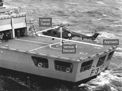
The approach and landing techniques vary, usually between countries. The following is that used by the Royal Navy. One aspect that needs to be emphasized is the lack of pilot’s vision below and behind the aircraft. Additionally, with a two-seat layout in the cockpit, the pilot sits in the right-hand seat when viewed from behind. A typical landing and take-off are illustrated below (see Figure 7.10).
|
|
|
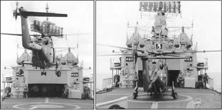
Figure 7.11 A Lynx landing on deck showing the operation of the undercarriage (Courtesy Agusta Westland) |
The approach is made on the port side of the ship with the aircraft coming in on a glide slope of about 3 °. This brings the aircraft to a hover – relative to the ship – at the hangar height and 1.5 to 2 rotor radii off the hull and superstructure. A traverse is then made parallel to the hangar door until the helicopter is hovering above the ship’s centreline. When the ship enters a quiescent state, the aircraft is lowered to the deck, with the aim of a firm touchdown (see Figure 7.10 and Figure 7.11). The undercarriage is designed to arrest the downward motion and also to kill off any tendency to recoil back upwards. If available, a reverse thrust can be selected for the main rotor, pressing the helicopter firmly onto the deck. The decklock is then activated providing a secure mechanical connection to the ship. The main rotor can then be returned to zero thrust. The undercarriage is often fitted with castoring wheels so the helicopter can be manoeuvred on deck using the tail rotor thrust to provide the turning moment.
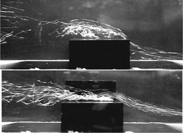
One item of particular importance is the flow conditions surrounding the flight deck. Ship’s flight decks are usually placed at the rear of the ship and with the hangar and hull sides, the flows are typically separating off sharp edges – that is bluff bodies. Figure 7.12 shows two flow types seen in a water tunnel experiment. Both flows are appropriate to wind perpendicular to the ship centreline. The upper image is just a hull and deck where the flow separates off the windward deck edge dividing the flow into a recirculating region above the deck surmounted by a clear airflow directed upwards. The lower image shows the effect of adding a hangar-type structure. There is now a separation line along the upwind hangar door edge. This combines with the original separation line to give a vortex flow which develops from the bottom door corner and covers the entire deck region.
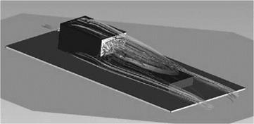
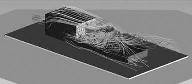
If the flow is coming from the bow, the flow is influenced by the hangar as shown by Figure 7.13 which is a computational fluid dynamics (CFD) calculation.
The flow is dominated by the separation off the hangar roof and its eventual reattachment on the deck surface. In reality this reattachment point varies in position with respect to time. It is to this flow state that the helicopter enters as it traverses over the flight deck. The rotor downwash will interact with this flow producing a typical pattern as shown in Figure 7.14.
The flow is completely changed with the rotor downwash providing the main feature. There is now a significant recirculation between the front rotor edge and the hangar door. It is these
|
Figure 7.12 Flow past a hull and a hull-superstructure combination |
|
Figure 7.13 CFD predicted flow over bow – ship only |
|
|
|
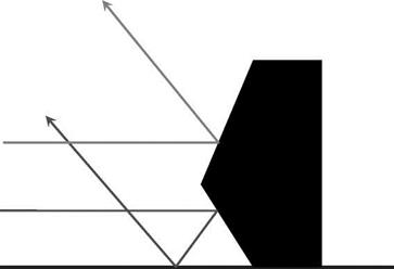
Figure 7.15 Stealth applied to ship profile |
|
|
effects which make shipborne operation so challenging for a helicopter. The separation off the ship’s superstructure will be made more complex with the new breed of warship. In order to introduce stealth the superstructure is significantly changed.
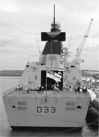
Figure 7.15 shows two incident signals from a radar source and by using inclined surfaces the signals are returned in a specific direction which will minimize any returns to the enemy source. This alignment technique has been used on the more modern fighter aircraft designs. Figure 7.16 shows the flight deck of a Type 45 destroyer, HMS Dauntless, where the inclined faces of the hull and superstructure can be seen.